
QRP Labs Ultimate3S WSPR Beacon Kit
QRP Labs offer a few kits which can beacon or transmit WSPR, and the kit I chose to build was the Ultimate3S. This post will serve to document my experience with this kit in particular.
If you are not familiar with the WSPR digital mode, watch David Casler’s video on WSPR. If you’re interested in WSPR, you can either report “spots” or stations you’re receiving (see my post on SDR WSPR Receiver) or you can transmit or beacon for others to report or “spot” you, or both. WSPR spots are reported to WSPRnet, where you can view spots worldwide. This is the centralized database or repository where all received WSPR beacons are reported to. There are a variety of apps and sites you can use to view the data either visually on a map or download/export for other purposes. I use the iPhone app WSPR Watch for visually viewing my results and to view each station’s details of the report.
The main purpose of WSPR is to be able to see, in near real-time, band conditions and open propagation paths. It can also be used to test, experiment, or compare different antennas, both for reception and transmission. Of course, this would assume there are always enough “spotters” or stations reporting what they hear, as well as enough stations beaconing or transmitting from various locations worldwide.
WSPR is an interesting mode because it is a one way transmission. It relies on internet availability and spotters (those that receive your beacon) to report to a centralized database.
If you’ve used FT8 before, you’re likely familiar with the WSJT-X software which is used for FT8 as well as other modes. One of the other modes this software can do is WSPR – it can both transmit and decode WSPR. Since WSPR is a weak signal mode, if you’re thinking of transmitting WSPR, be sure to limit your power output to 5 Watts or less. Many modern HF transceivers can be connected directly to a computer running the WSJT-X via a “sound card” interface built into the radio. In addition, many of these transceivers can output 5 Watts or less if you dial back the power. However, dedicating an HF rig to receiving or transmitting WSPR may not be desirable, which is where a dedicated WSPR beacon can be useful.
I chose the kit approach (as opposed to buying something pre-assembled) because I wanted the experience of building something that I can easily troubleshoot and understand. In addition, I wanted to keep the cost low. Buying or dedicating an HF rig and a PC for beaconing is a tad more expensive than this kit is. At the time of the writing of this post, the starter kit from QRP Labs cost just under $36 USD. For those unfamiliar with QRP Labs, their kits often contain parts or sections from their other kits. This allows for some serious customizations or “upgrades” to the base kit. The kit has some modules which themselves are “kits” which can be purchased separately for other kits or projects. The assembly uses a “stacked” PCB design, meaning several PCBs are interconnected by standoffs and headers. This is a great design for troubleshooting should something not work correctly after you build it.
QRP Labs has excellent documentation on this kit and all of the options available. The assembly instructions are very detailed and include pictures and notes on each of the options available when building the kit. Be sure to download and read all of the documentation before beginning. This will allow you to mark up sections of the instructions which are applicable to your preferences and customizations. You’ll want to avoid having to remove parts or cut jumpers if you can.

Kits can require various skills, tools, and parts otherwise not supplied with the kit. This kit requires intermediate building skills in my opinion. This is mainly due to the small PCB sizes and various options available. You will need a soldering iron with a fine tip, rosin core solder, hookup wire, and a DVM (digital volt meter / multimeter). Depending on your eyesight, you may want to be sure to have a lighted magnifier and a “helping hands” soldering station. If any mistakes are made, you may need to be prepared to desolder, have replacement parts handy, or come up with creative solutions.
The kit requires a well regulated 5V DC supply, which is not a customary voltage for amateur gear. I chose to use a DC to DC converter, in this case one that can take 8-22V input and keep a constant 5V output. This allows me to run the kit from a 12V battery or a 13.8V power supply.
In this post I include quite a bit of additional options or methods for assembly which I believe are upgrades for convenience, not necessity. Of course, these options add to the cost of the kit.
Browse the various options for this kit on the QRP Labs site – determine whether the starter kit suits your needs, or whether you find some of the add-ons are necessary, or whether you would like to purchase all of the add-ons. I’ll attempt to give an overview of these add-ons and why I chose to include them in my kit.
6 Band Relay Switched LPF Kit

I chose the deluxe 6-band kit because I couldn’t decide on a single “band” I wanted to transmit on. The design of this kit uses a low pass filter for each band. For example, if you order a kit and choose the 20-meter band, you can always order additional low pass filters for the additional band(s) you wish to transmit on. These low pass filters are removable/interchangeable and are placed on the main board using a header and socket. The deluxe 6-band kit includes 6 filters: 80, 40, 30, 20, 15, and 10 meters.
The deluxe 6-band kit includes a relay board which can switch between the 6 bands. 5 of these filters are placed on the relay board, and the 6th is placed on the main board. It should be noted that 6 bands will require 18 toroids to be wound, as each filter board has 3 toroids. You will become an expert at winding toroids if you order a kit with all 6 bands!
I chose to start my build by assembling the Low Pass Filters. This was the most tedious part of the kit to assemble because of the number of toroids to be wound. The kit came with plenty of magnet wire, even a bit extra of you accidentally pull too hard when winding and break the wire. In my experience, any kinks in the wire are guaranteed to be points of failure where the wire will snap. Carefully unfold each section of magnet wire!
The instructions mention a method for soldering the magnet wire from the toroids to the PCB traces using heat from your soldering iron. This should be done carefully – too much heat can damage components and/or the PCB. However, I found this method to be a success. Checking for continuity after soldering these is easy with a DVM across the input and output terminals of the assembled module.
I recommend using a fine point permanent marker to write the band on the bottom of each assembled filter, such as “20m”. This way you won’t find yourself counting turns on the toroids to determine the 10m filter from the 15m filter. The location of the filters becomes important for assembly and operation.
Lastly, I wanted to solder a right angle SMA connector to the RF output on this board so that I can easily disconnect it and remove it from the case for troubleshooting if needed, but there just was not enough room in the case for it to fit with a right angle SMA cable attached. I ended up soldering a short piece of mini coax with a female SMA connector on the other end to the RF output on the relay board.
QLG2 GPS Receiver Kit
WSPR is one of the digital modes which requires all transmitters and receivers to by synchronized within a second (more or less). While you can set the time yourself when operating the beacon, it’s far easier to have this automatically set and maintained via GPS module. Further, the GPS module provides a 1 second pulse which the Ultimate3S uses to calibrate the crystal oscillator. WSPR is one of the digital modes which requires the transmitter (and receiver) to have no more than a hertz (or so) of drift during its 2 minute message duration. Crystal oscillators can drift from temperature changes; having the GPS module allows for the Ultimate3S to “calibrate” after each WSPR transmission to adjust for these changes.
The latest iteration of this kit uses the same size PCB as the others in this kit, which means you can attach it to the back of the “stack”. If you’re adding a case to your build, this means the GPS receiver will be inside the aluminum box and you will need a way to bring the external antenna into the case and connect it to the PCB.
I recommend soldering the included SMA connector in a vertical configuration, as the horizontal or right angle attachment will not fit inside the case. Or, solder a right angle SMA with the angle inward toward the surface mount GPS sensor. Be careful when placing any SMA connector on this board as there is a trace that the connector may contact when soldered flush against the PCB. The instructions clearly indicate this, and I used small zip ties to keep the connector elevated off the PCB a bit while I soldered it in place.

I recommend purchasing a short male SMA to female SMA bulkhead cable to run between the SMA on the GPS board out to the back of the case (and drill the appropriate hole in the case). This will allow you to connect and remove the GPS antenna as needed.
OCXO (Oven Controlled Crystal Oscillator) or TCXO (Temperature Controlled Crystal Oscillator)
The TCXO kit provides a more precise crystal oscillator which will not vary with temperature (within its specified limits). The module uses an oven or heater to keep the crystal at its specified frequency, and can adjust the amount of heat using a feedback loop. This kit isn’t necessary but it does reduce the need for significant or frequent adjustments during the calibration process after each WSPR transmission, and is not a very expensive option. If you’ll be using your beacon outdoors or in locations where ambient temperature changes, this would be a good option to add.
5W PA Kit
WSPR is a low power mode and you can be heard around the globe on 200mW of transmit power (conditions permitting of course). I chose to add this option for future expansion should I decide to experiment with more power. This might be useful if your antenna doesn’t have gain, or, is otherwise a compromised antenna. A bit of extra transmitting power can help offset those conditions. Adding this power amplifier will provide around 5W from 12V of supply voltage, given about 200mW of input power. When building this kit, I made sure that I could easily add this as an option later, and I plan to run the kit without it at first.
Aluminum Case
Adding the aluminum case is necessary in my opinion because it ensures the kit doesn’t get damaged when moving it. It keeps components such as the toroids from becoming damaged, and various other accidents that can happen with an exposed kit. Since the kit has several PCBs, an RF output and a power input, it’s best to secure everything in a case. This way the beacon can be moved or used as a portable unit if desired.
Final Assembly
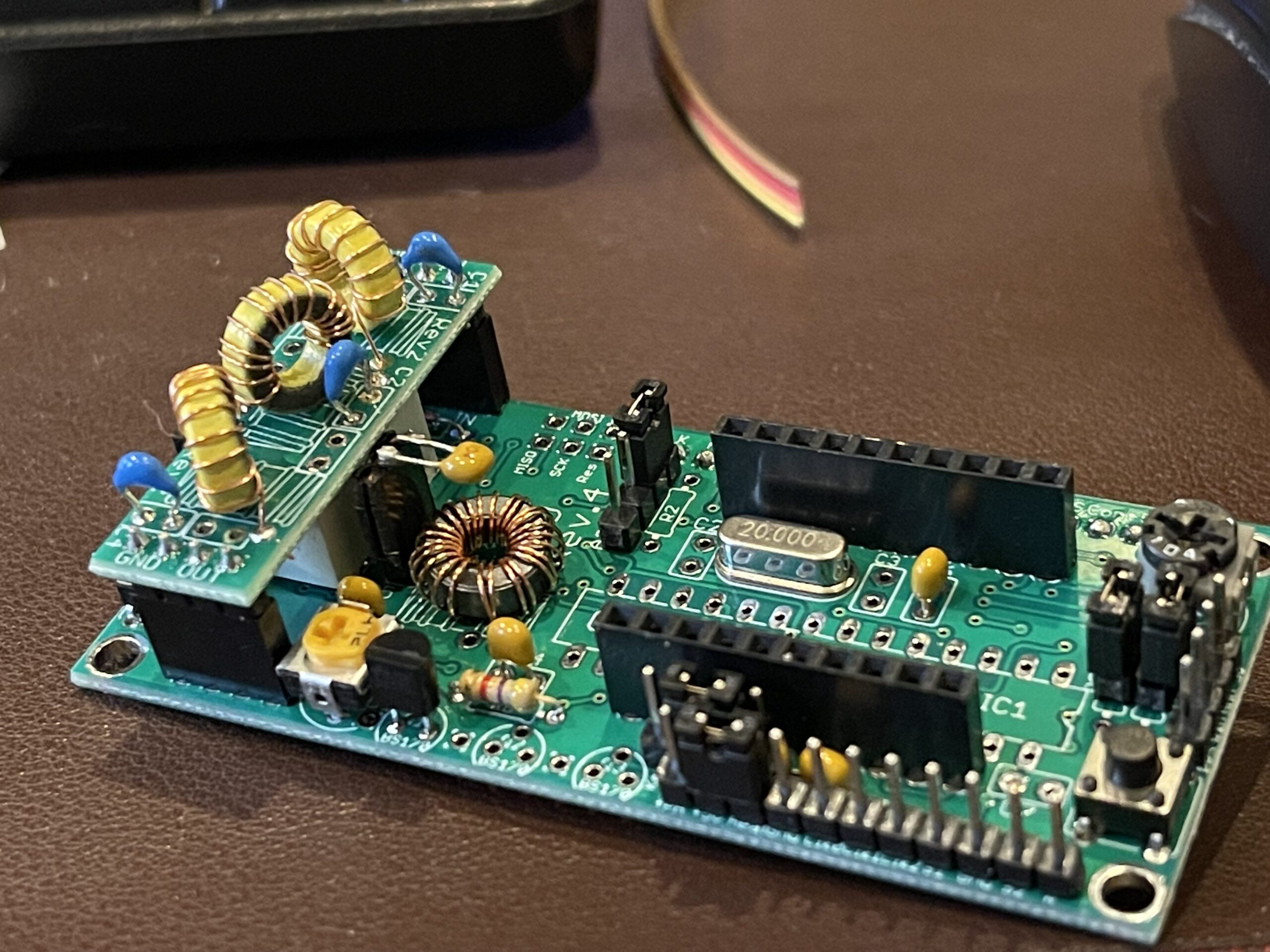
The final assembly involves attaching several PCBs together in a specific order (from front to back): LCD display, main PCB, Si5351A Synthesizer kit, 6 band LPF relay kit, GPS module (5W PA can be added at the very back of the stack).

If you are using the GPS module, you will need to build a connector from the main PCB to the GPS PCB. I purchased a set of headers and sockets for various uses, including this connector. You can break off a section of the male pin header as needed (in this case 4 pins), and solder them into the position for the GPS connection on the main PCB, and the same on the GPS board. I then used the female part of the connector and a fine snipping tool to break off a 4 pin section. I then soldered a 4 conductor ribbon cable between 2 female connectors.

I used some small shrink wrap over the soldered connections to ensure no shorts will occur between the posts. This connector allows me to attach or disconnect the GPS if needed. I created the same type of connector for the power connector to the main PCB.
Whenever a “jumper” was mentioned in the instructions, I soldered in a male pin header instead, and used jumpers if I wanted the jumper in place. This way I can add/remove the jumpers to alter the configuration rather than cutting or soldering jumpers in the future.

One of the options is to use the 5W PA kit and since I wanted to add that option later, I decided on the 25-turn toroid winding on the main board as opposed to the bifilar turns option. This way the kit will work equally well with or without the 5W PA kit. In addition, I didn’t solder C5 in place on the PCB. Instead, I used another post and jumper to be able to remove or add C5 as needed. Because there is a PCB above the main PCB, this capacitor needed to be soldered in horizontally to make room.
You’ll notice the other header strips and jumper pins I’ve soldered to the board during the build.
When placing the low pass filters on the relay board and main board, jot down which band is installed at each position (0-6). Later on when enabling a transmitting mode, one of the parameters is which relay to activate in addition to the transmit frequency. Keep that list handy in a binder or perhaps taped to the bottom of the case.

The aluminum case has enough room for the entire PCB stack (including the GPS module) and a DC to DC voltage regulator if you choose to enclose that inside the case.
I used a similar style of header connection for the two buttons (menu and edit) to the PCB as I did for the GPS connection and the power connection. If you look closely at the GPS board (the last board in the stack), you’ll notice I soldered the right angle SMA connector so that the connection faces the GPS sensor. If it were to be soldered in any other direction, there would not be enough room inside the case to attach the coax jumper. I used a right angle connector instead of a vertical connector in case I add the PA to the top of the stack in the future.
I oriented the GPS board so that the USB connector would be facing up (in case I need to perform a firmware update). Notice the Atmel AVR programming connector pin header is accessible, in case a firmware update is needed.
Each connection between the PCB stack and the switches, buttons, RF connections and power can be detached in case I need to remove the boards from the case.
In the future, I may connect the serial output from the GPS to the 9-pin DIN connector in the back of the case. This would allow me to use the GPS with other devices, such as the FT-991A.
 |  |
Smoke Test

Powering up the kit for the first time can be exciting or a disappointment. If you’ve carefully installed the components and ensured no solder bridges or shorts, there’s a near 100% chance it will be a success. The designers of this kit and the included instructions are very detailed and thorough. When powering up for the first time, the software keeps the program in a diagnostic state, and no RF output will occur. Further, even when configuring your call sign and other parameters, all transmission modes are disabled by default. This allows you to verify the GPS connection and signal, the LCD display, and other connections. I had complete success on first power up all the way out to an actual radiated RF signal.

Before connecting the kit to my antenna, I needed to adjust the bias for the on-board PA (power amplifier). Initially the bias is turned all the way down, so that there is effectively no significant RF output. The instructions mention several ways to set the bias, and the method I chose was to use an oscilloscope while transmitting into a 50 ohm dummy load. I adjusted the bias very conservatively – I adjusted it to about 75% peak power output (I turned the bias up past the peak voltage readout on the scope then dialed it back to about 75% of that maximum reading).
On 40 meters, the scope indicated 4.45 volts RMS, and using the formula(s) discussed in the General Class study material, the corresponding wattage was 396mW on 40 meters (4.45 squared divided by 50). On 20 meters my measured output was 223mW, on 10 meters my measured output was 231mW.
The final output transistor was barely warm to the touch at that power level after a 2 minute transmit cycle. My main HF rig can’t possibly run that cool for the same duty cycle (it has a variable speed cooling fan that serves as a notice to the operator when it’s working hard).
Operation
In order to begin transmitting WSPR beacons, you will need to enable at least one of the “modes” as described in the operation manual. There are 16 modes (or channels) total. I am referring to these as “channels” to avoid confusion between these programming slots and “modes” of transmission, such as WSPR, CW, Opera, etc.
By default, all of the channels are disabled. You can configure one or more of these channels for any one of the modes that this kit is capable of. Since this post is related to WSPR, I’ve enabled only WSPR modes. To get started, I enabled channel 0 for WSPR, set my output relay to the 20 meter slot, and chose 14,097,082 Mhz as my output frequency.

Setting the output frequency requires some careful consideration to make sure you’re within the WSPR bandwidth for the WSPR receivers. Similar to FT8, you have “slots” within the WSPR bandwidth, each being 6 Hz wide. If two or more stations transmit in the same “slot” at the same time, then that can possibly affect the ability for receiving stations to hear one or both of those transmitting stations. You can find the WSPR frequencies in WSJT-X, and these are the base or “dial” frequency (0 Hz offset). For example, on 20 meters the base or dial frequency is 14,095,600 Mhz. The actual center of the bandwidth for WSPR is 1,500 Hz above this base. The bandwidth starts at -100 Hz from this center and ends at +100 Hz from this center (total WSPR bandwidth is 200 Hz). This means you have the frequency range of 14,097,000 Mhz to 14,097,200 Mhz. Choose a frequency between these two and at 6 Hz increments.
One of the other operating parameters you will need to set is how often you transmit your beacon (frame setting). In my experience, and with avoiding multiple stations on the same frequency at the same time in mind, I experimented with a period which would be different than the default might be, such as 2 or 4 minutes after the start of the hour, and 8 minute increments.
Lastly, based on your power measurements, be sure to set the appropriate power level (in dBm) for each band you’ll operate on, within the WSPR settings on the channel you are configuring.
Band Hopping
Assuming your antenna is resonant on multiple bands, or, you have a QRP auto-tuner, this beacon can band hop. This is accomplished by enabling several channels in WSPR mode, each on a different band. The Ultimate3S will begin at channel 0, then run channel 1, 2, etc (for only the channels that are enabled).
Results

Within the first 24 hours of transmitting my WSPR beacon on 20 meters from northern New Jersey, I had reports from stations in Australia, Iceland, and Antarctica.
The station in Antarctica is DP0GVN, is a club station located at the German Antarctic Research Station “Neumayer III” in Dronning Maud Land, Antarctica.
I connected the beacon to the MFJ-2012 OCFD installed in the attic, through an MFJ-969 tuner.
After this initial test, I do not think I will be using the 5W PA kit, as I feel that more power is unnecessary based on my experience to date.
Final Comments
I highly recommend this kit for anyone who is looking to build something themselves as a beginner or intermediate kit builder. QRP Labs did a fantastic job on the build, quality of the parts, and quality of the instructions.
QRP Labs have a groups.io forum for their kits, should you have any questions or issues.
Update
I’ve successfully connected the QLG2 GPS kit to the FT-991A and PC for APRS. It involved adding header pins to H2 and adding a TTL to RS-232 converter. I’ve added a post on this connection here.
