


Connecting the QRP Labs QLG2 GPS Kit to the FT-991A
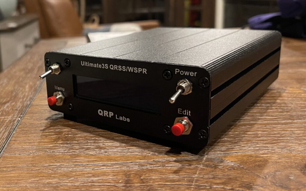
Awhile back I assembled the QRP Labs Ultimate3S WSPR kit. I chose to add the QLG2 GPS kit to the WSPR kit for the automatic grid square determination and 1pps signal for frequency and time sync accuracy. I wanted to be able to use this GPS receiver for other purposes in addition to WSPR such as my FT-991A and an APRS digipeater.
The FT-991A supports C4FM on 2 meters and 70 cm, and your current GPS coordinates can be sent along the data channel to the receiving parties. This useful for other C4FM transceivers because they can display the distance between the receiver(s) and the station transmitting. In addition to distance display of the transmitting station, the FT-991A has a time display at the top of the screen. An external GPS connected to the FT-991A can be an easy way to set these properties automatically. This is especially useful if using the transceiver portable.
The QLG2 kit is used in other QRP Labs kits, such as the shack clock and QCX in addition to the Ultimate3S.
The QLG2 kit includes a virtual serial port via USB, which allows for connection to a PC or Raspberry Pi (or other USB hosts) to communicate with the GNSS module by default. This means that it’s possible to send and receive commands to and from the GNSS module with a terminal emulator on the PC, for example. Due to the lack of space inside the case of the WSPR kit when assembled, I did not run this USB connection to the outside of the enclosure. This could be done by swapping out the included USB connector for a micro USB connector and adding a bulkhead USB connection to the outside of the WSPR enclosure. While this would work with a PC or Pi, I wanted a direct RS-232 output for the FT-991A and digipeater.
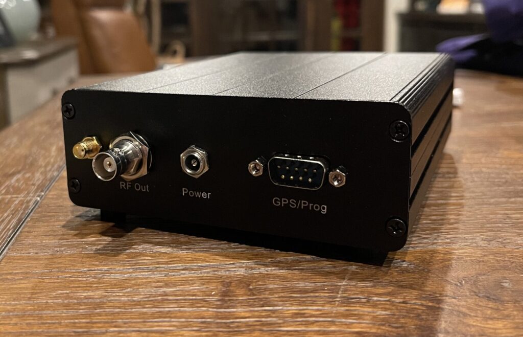
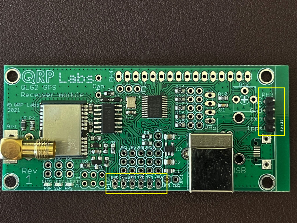
The QLG2, when used in the WSPR kit, has a 4-pin header (PH3) with GND, 1pps, +5 volts to power the QLG2, and the serial data output (TXD) from the QLG2 kit to the WSPR kit. This header (PH3) is highlighted on the right side of the picture below. The other header on the bottom of the picture below (PH2) also has the serial data output (SER) and ground (GND). My idea was to connect the SER and GND pins from PH2 out to the DB9 connector on the back of the WSPR kit so that it can be connected to additional devices.
NMEA Data Stream
The signal from the QLG2 TXD line contains the NMEA data stream, which is transmitted every second at 9600 baud, 8, N, 1. These settings are the defaults configured by the jumpers and microcontroller firmware on the board upon power up (some of these parameters can be changed if needed). The NMEA data stream is ASCII text. Devices which can receive GPS data are most likely looking for the NMEA formatted data stream, such as the FT-991A for example.
The TXD line (TTL logic level) is normally high (+5V), and pulled low (0V). The QLG2 buffers the output from the GPS module (at 3.3V CMOS level) to the supply voltage level (5V) when it feeds it to the WSPR kit via the TXD line.
I connected a scope to the TXD line to verify the baud rate and the TTL level:
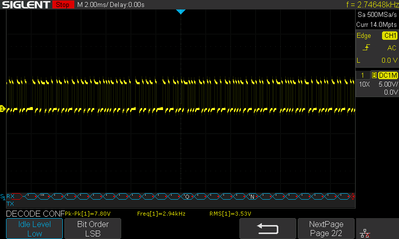
Attempting to decode this serial data as ASCII directly from the TXD pin as if it were and RS-232 line or UART line does not work, as the signal is inverted. In the picture above, you can see that the characters decoded are not what is expected in the ASCII NMEA sentences.
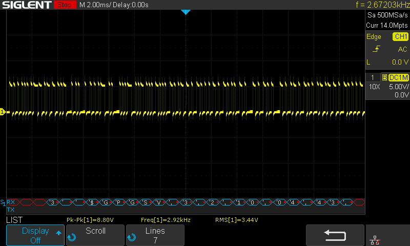
When changing the decoding to idle level high (as found in TTL circuits), the ASCII decoding works as expected. From the picture above, the start of an NMEA sentence with $GPGSV is seen (this is the sentence that describes the satellites currently in view).
TTL to RS-232 Converter
Since I want to connect this serial output from the TXD line to the FT-991 and/or a digipeater, I need an RS-232 output. RS-232 differs from TTL in that the signal on RS-232 is inverted and the voltage is higher:
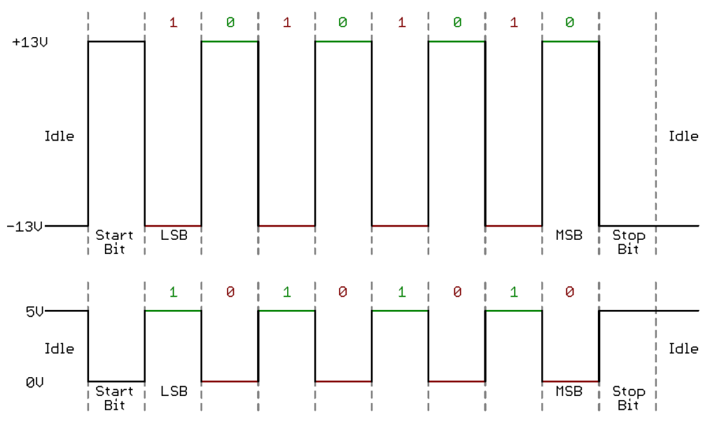
The top half of the picture above is an example of RS-232, while the lower half is TTL. Fortunately, there’s an IC which converts TTL to RS-232, the MAX232. And, as luck would have it, there’s a pre-assembled version of these with a DB9 connector:
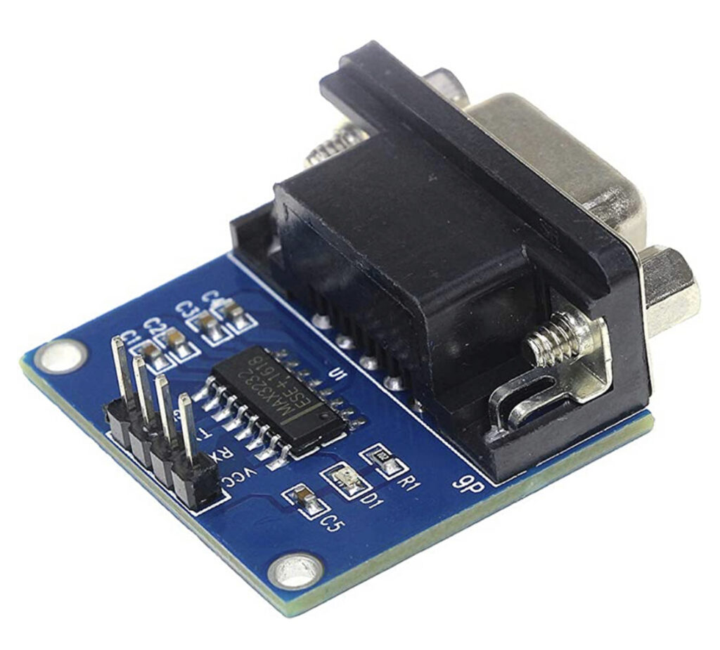
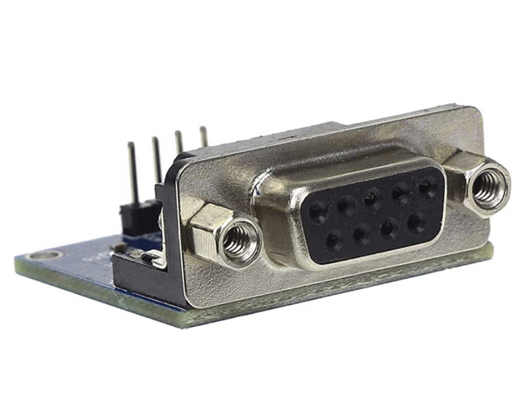
These can be powered by 5 volts, which I can tap from the QLG2 module on PH2, as well as the SER and GND as input to the converter. I was able to fit one of these right where the DB9 connector opening is on the WSPR enclosure:
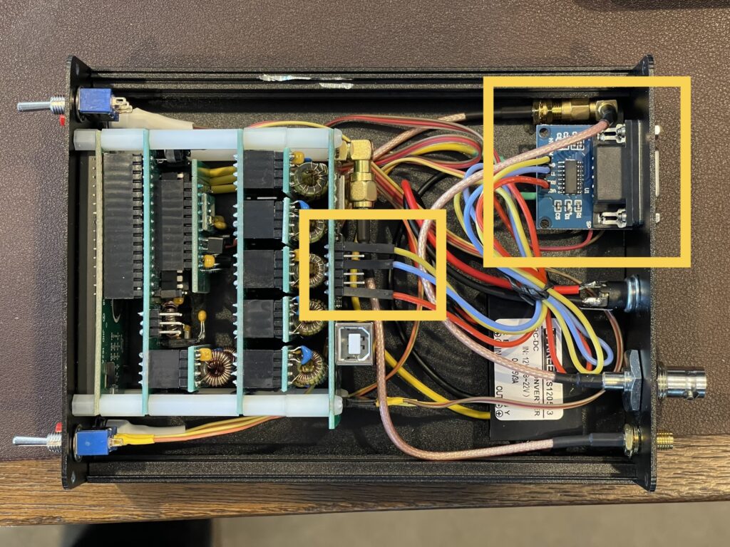
This time I used the dupont style jumpers which attach directly to the leads on the headers. This isn’t the most cost effective way to wire up the converter, but for testing purposes I am able to move the jumpers around if needed (for example if you reverse the RX/TX connection on the converter). I connected the SER line from PH2 to the TXD line on the converter, VCC and GND.
RS-232 Patch Cable
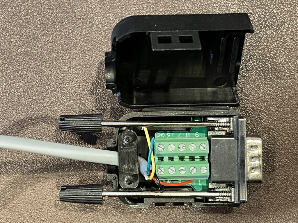
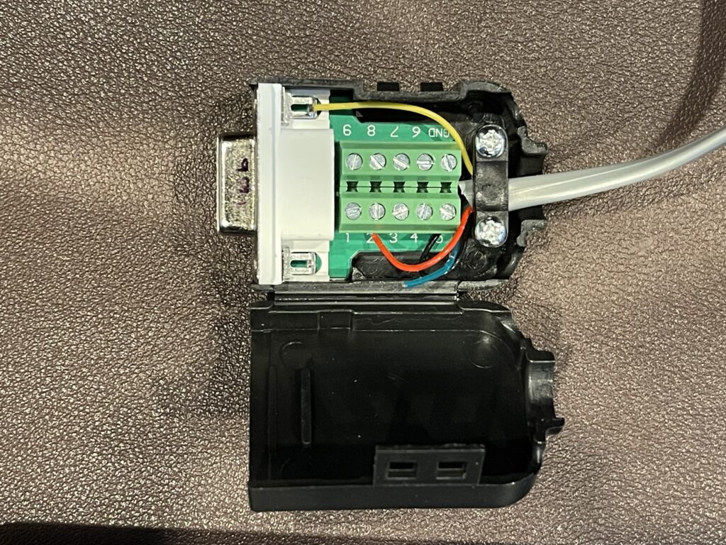
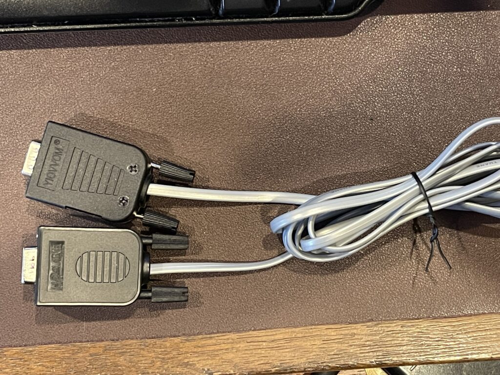
I assembled a serial patch cable to connect the output from the WSPR beacon to either a PC or the FT-991A. The serial patch cable has pins 5 and 2 wired together (pin 5 and 2 connected together on both ends). Building the RS-232 patch cable was simple – only 2 conductors were needed: GND and TXD. I used DB9 breakout connectors (one male one female) because they’re easy to wire up without soldering and they can be reused for other projects and cables. I reused an old telephone patch cable for nostalgia.
PC Test
After wiring up the TTL to RS-232 converter, I powered up the WSPR kit and connected the output of the RS-232 connection on the WSPR kit to a serial port on a PC with the serial patch cable.
I then used PuTTY to view the NMEA data stream coming from the GPS kit:
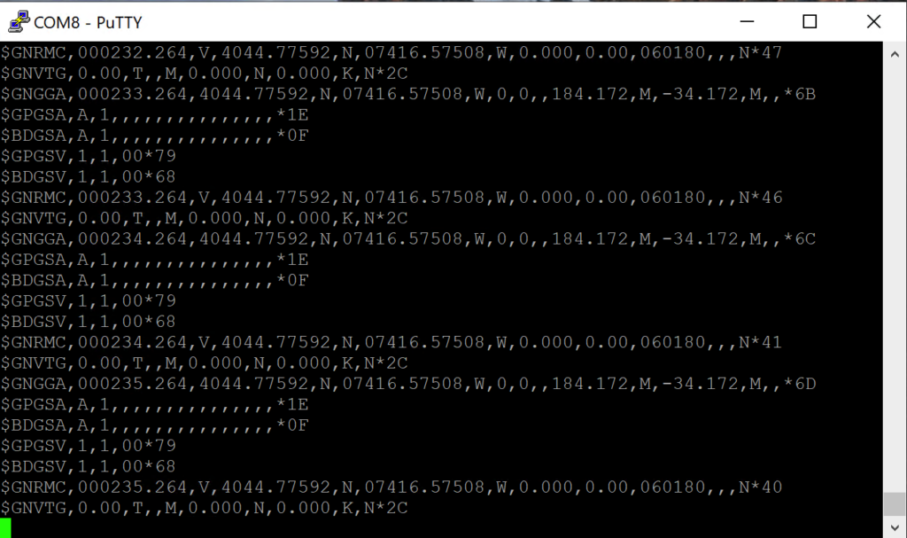
From this test, we can see the NMEA sentences with the various types of data from the GPS. The GPS module can be configured for which data types should be included in this stream. Since the transmission happens once per second at 9600 baud, there is a limit to the amount of data that can be sent every second at that baud rate. If you configure the GPS to send more than can be sent in that window, corruption or truncation of the output can occur.
APRSIS32 Connection
I also plan to work with APRSIS (or other APRS programs) for Windows, since I have the ultra portable windows PC to work with for other digital modes. I can pair this GPS receiver with the KPC-3 for a portable digipeater either at a field site or mobile. I do realize I can buy a GPS dongle for a few bucks and plug it into the PC, but where’s the challenge in that?
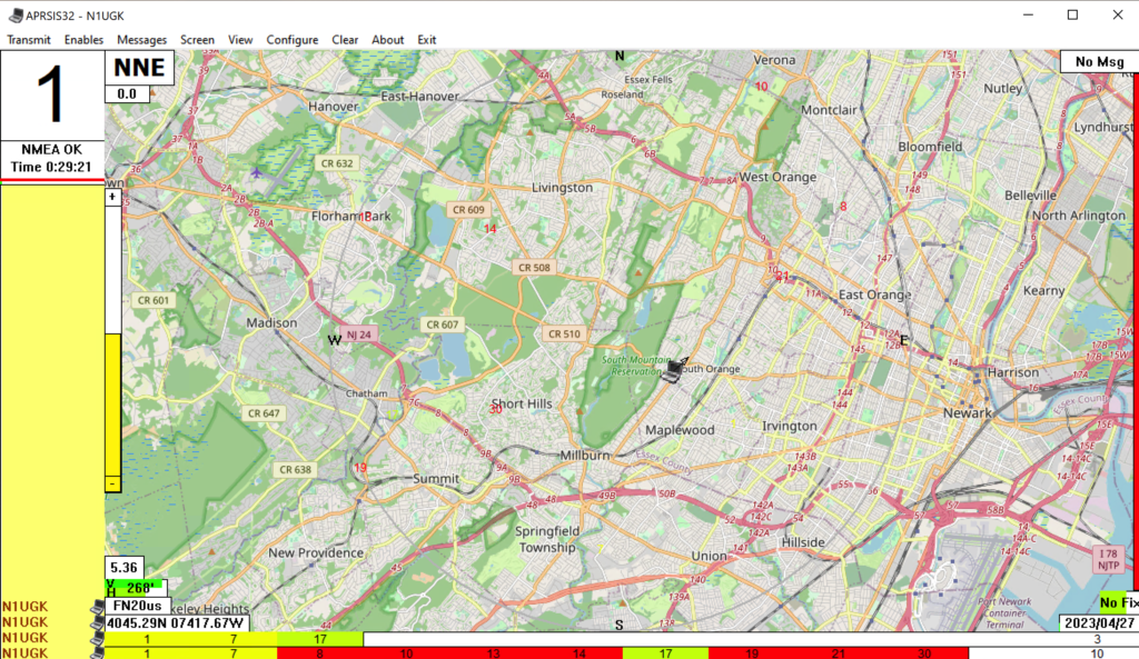
I configured APRSIS to use COM8 for the NMEA GPS receiver and although not very accurate indoors, it does work quite well otherwise:
FT-991A GPS Connection
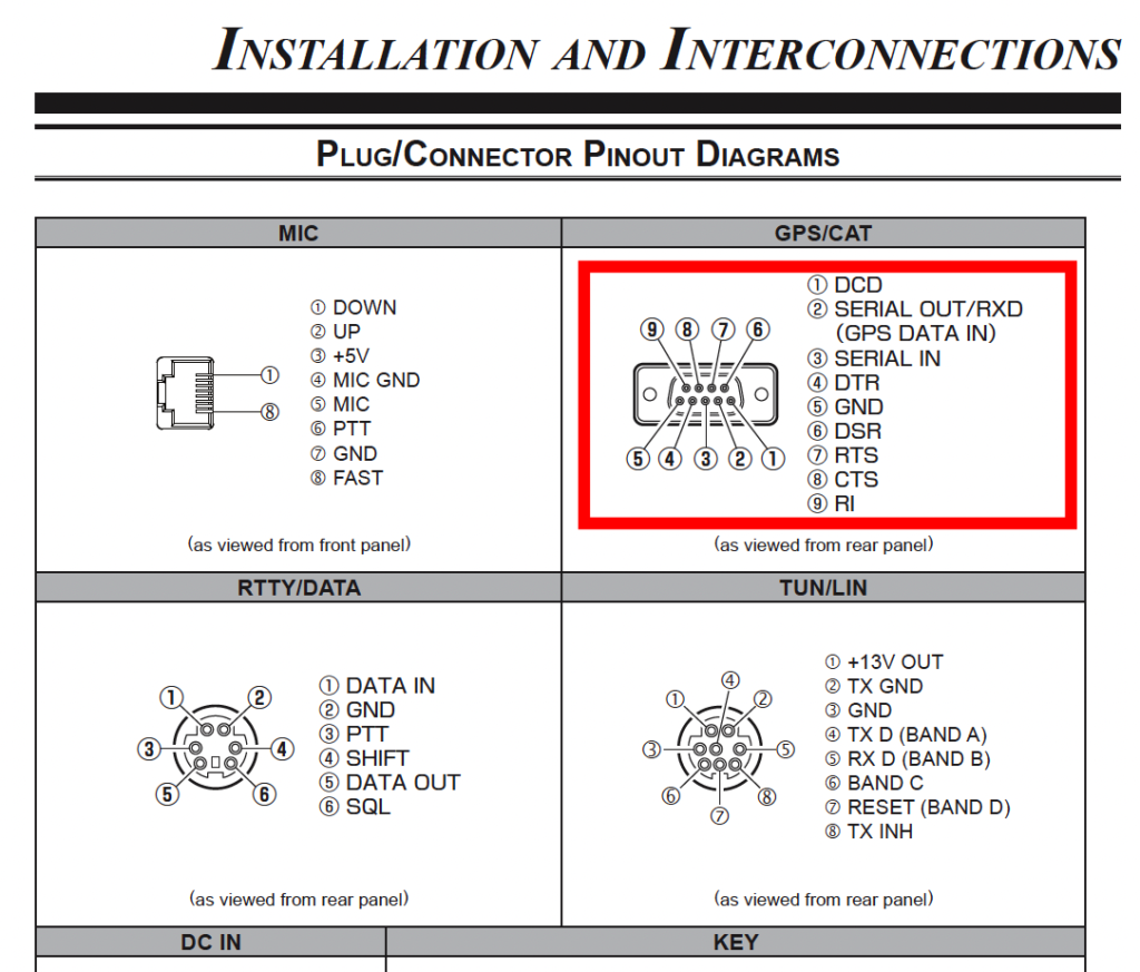
The FT-991A accepts a GPS input via it’s GPS/CAT port in the back of the rig. This port is dual purpose as it is used for either CAT control or a GPS. Menu item 028 can be toggled between RS232C, GPS1 or GPS2. The latter two switch the port for GPS data in on pin 2 of the DB9 connector, which allows for the same serial patch cable for the PC to be used to connect the FT-991A:
After connecting the WSPR beacon GPS output to the FT-991A input, and within a few seconds I was able to see the GPS indicator on the FT-991A:
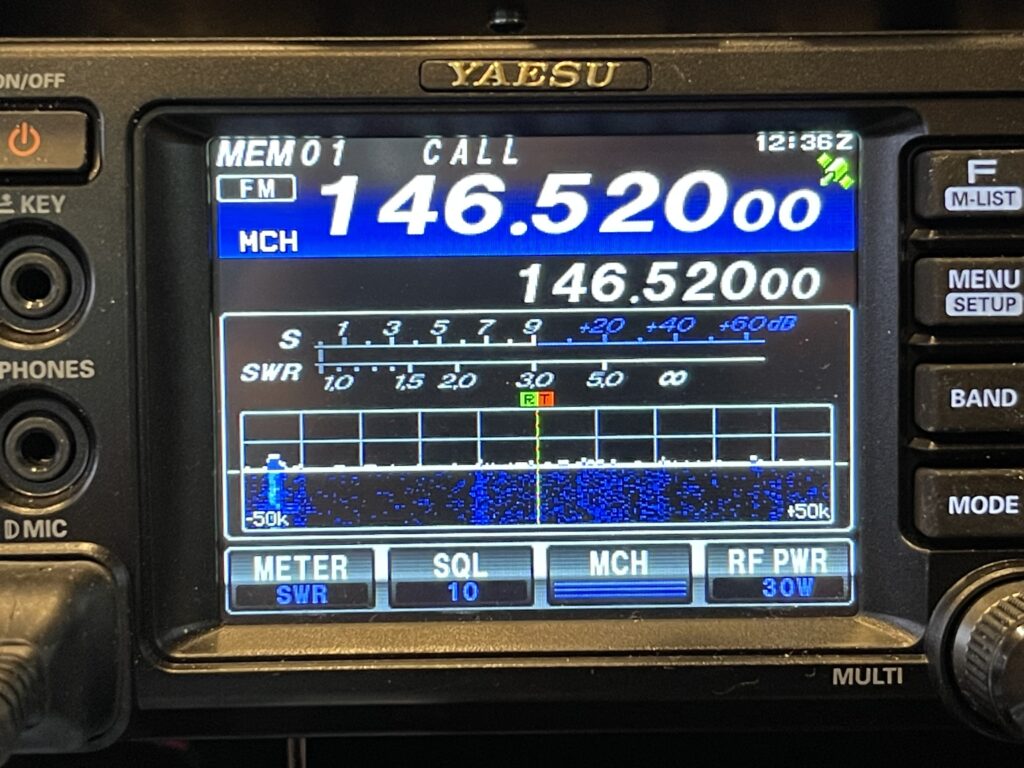
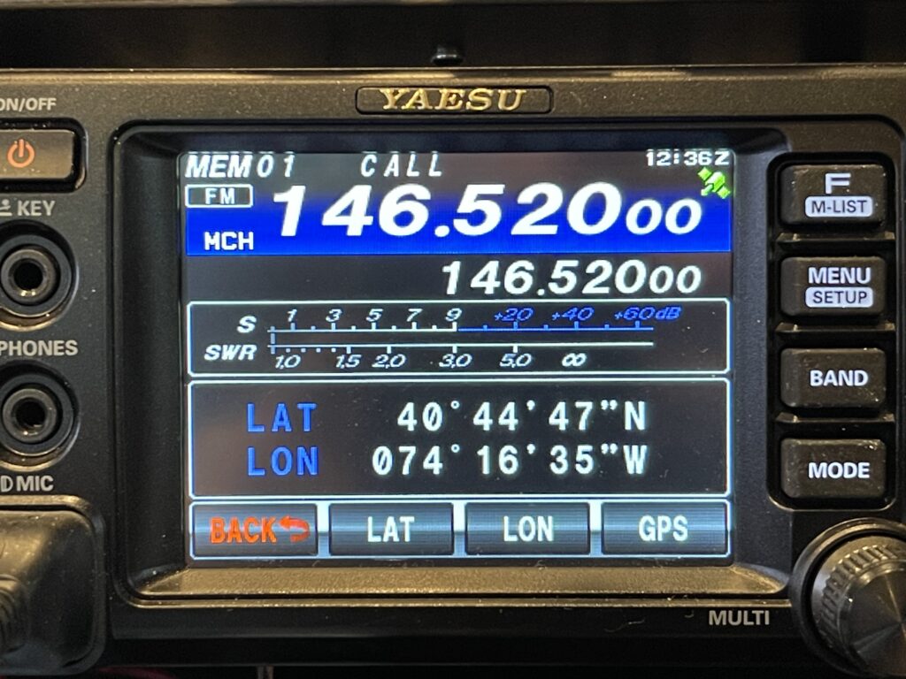
Both the Lat/Lon were updated when I pressed the GPS button as well as the time.
Results
After adding a TTL to RS-232 converter module inside the WSPR kit and building a serial patch cable to connect the WSPR beacon to the FT-991A / PC, the result was a success! The WSPR beacon can be powered on and either beaconing or idle, as the GPS module always outputs its serial data sentences. The same serial data is fed to the WSPR beacon main board and the FT-991A or PC at the same time.