
Assembling the “High Bands” (tr)uSDX Kit
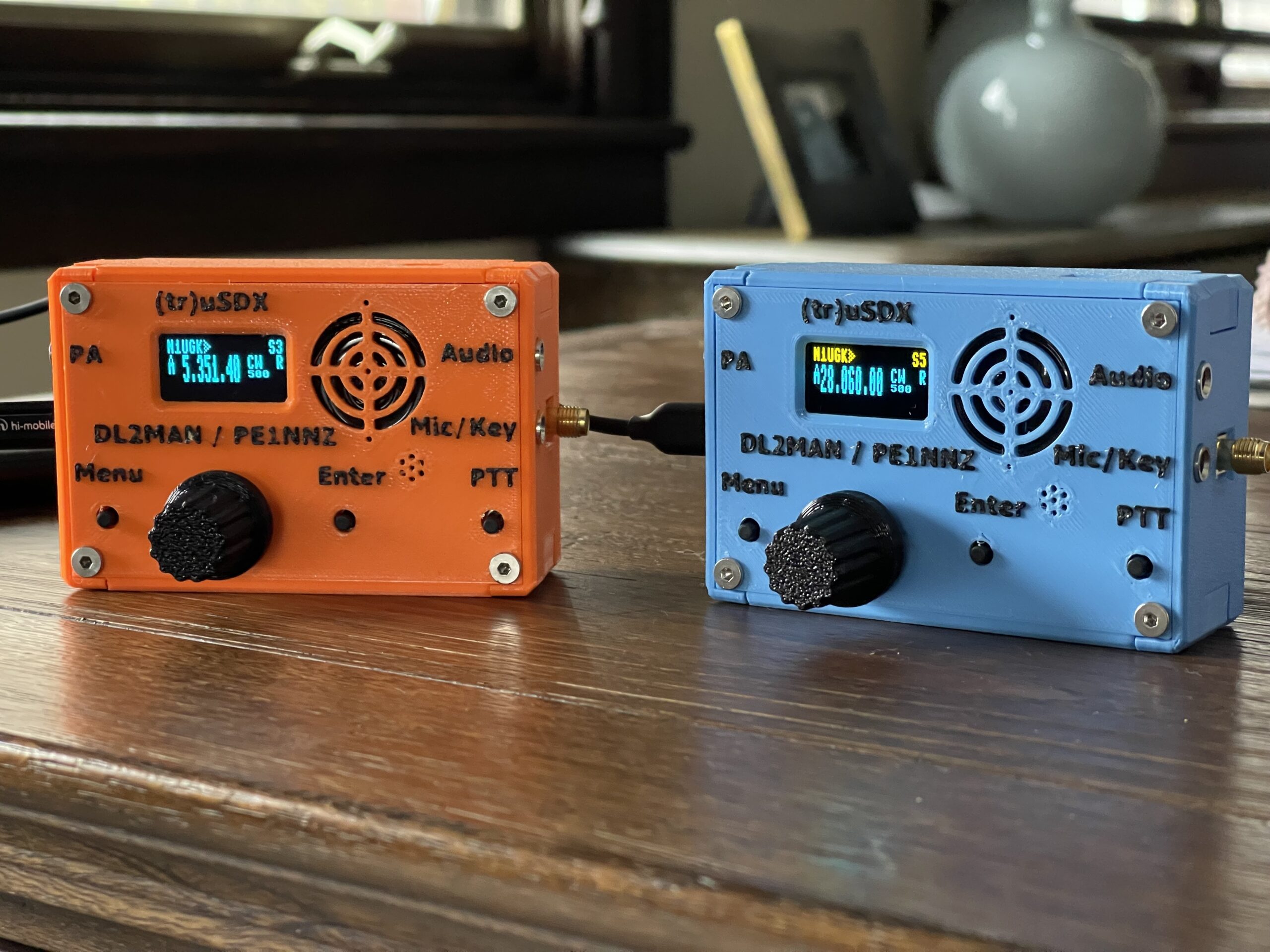
After assembling the low bands version of the (tr)uSDX, I decided to try the high bands version of the kit, which includes 10, 12, 15, 17, and 20 meters. I mainly wanted the 10 meter band as we are on the upswing of the current solar cycle.
The kit I chose this time was from Ali Express, and the case from the same vendor as my previous order, New DIY Tech.
The main difference with the high bands version is the RF board. The toroid windings and cores are different, as well as the FET for the final amplifier. The low bands version uses 3 BS170 FETs while this version uses a single surface mount FDT86256 FET.
The instructions mention that the spacing on the windings are more critical in this version due to the low number of windings for the higher bands.
The assembly was far quicker this time around, since I had experience with the first kit. The OLED mounting was easier since I decided to use the standoffs and bolts the kit included rather than making my own with spare header pins.
This kit had one minor difference with the header connector between the main board and the RF board. The spacing was about a millimeter too much, so the main board sat a bit too high up in the case. This was minor, and is hardly noticeable when it is fully assembled in the case.
In addition, this kit has a 2 color OLED display – the top line is a different color than the rest of the display.
Initial Testing
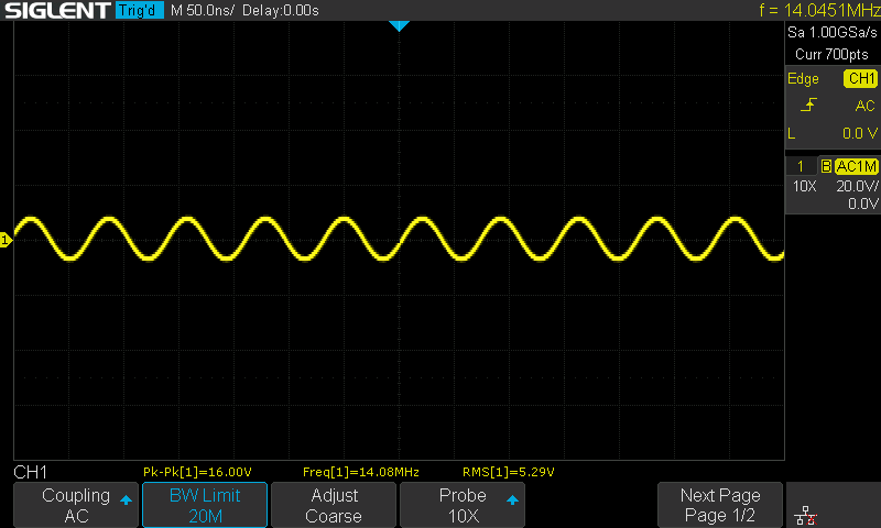
I tested the power output on all 5 bands for both a 5 volt source and a 12 volt source. I measured the output power using a scope while the rig was connected to a 50-ohm dummy load.
The following are the measured output power levels for each band using a 5 volt supply:
| Band | Measured Output | OLED Indicated Output |
| 10 meters | 0.51 watts | 0.59 watts |
| 12 meters | 0.52 watts | 0.64 watts |
| 15 meters | 0.67 watts | 0.75 watts |
| 17 meters | 0.49 watts | 0.47 watts |
| 20 meters | 0.55 watts | 0.46 watts |
The following are the measured output power levels for each band using a 12 volt supply:
| Band | Measured Output | OLED Indicated Output |
| 10 meters | 1.78 watts | 2.66 watts |
| 12 meters | 2.83 watts | 3.90 watts |
| 15 meters | 3.38 watts | 4.17 watts |
| 17 meters | 2.72 watts | 2.95 watts |
| 20 meters | 3.32 watts | 3.20 watts |
Harmonics
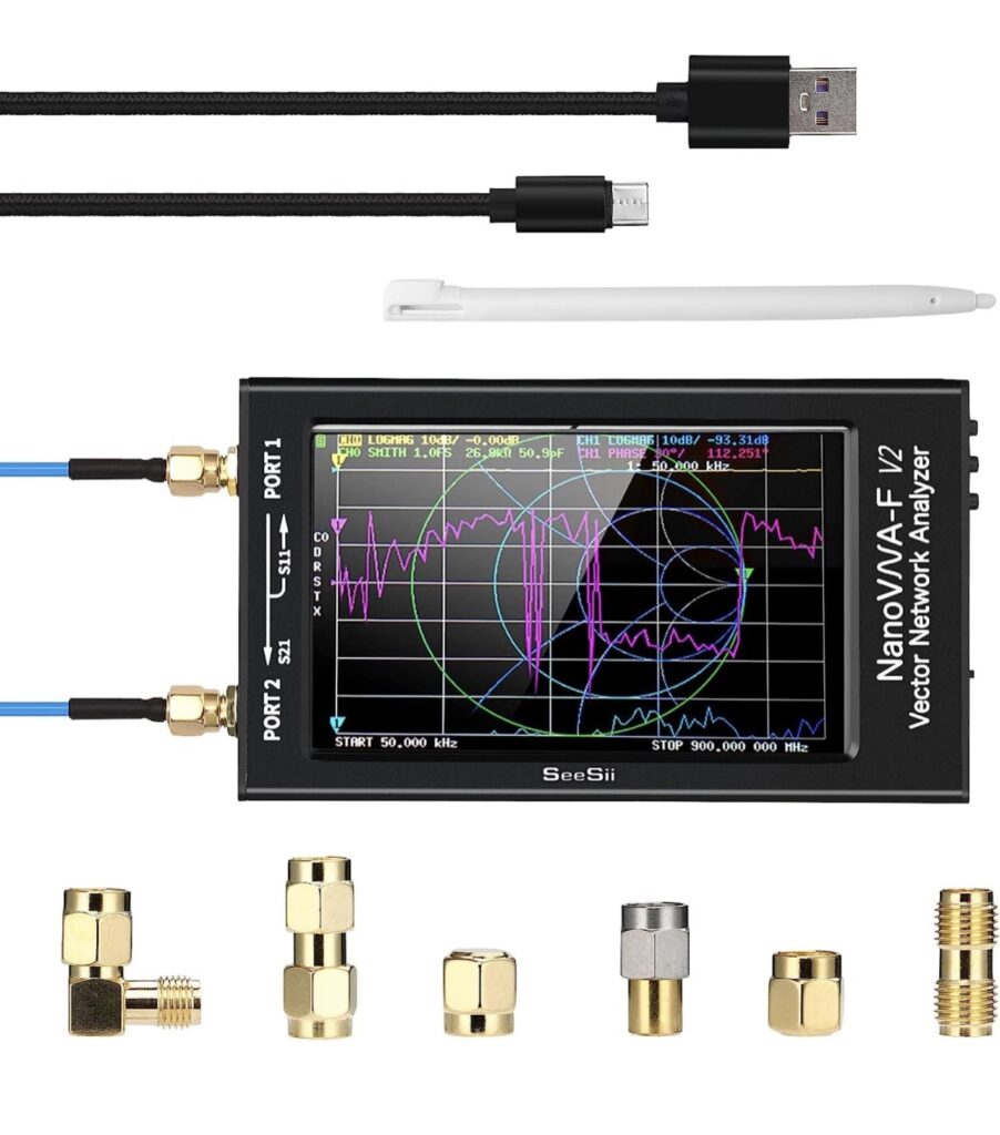
I measured the harmonic output on this version to see if the winding spacing on the toroids needed adjusting. My approach to this was to use a nanoVNA. I followed the procedure that DL2MAN explained in the assembly video.
For those who are unfamiliar with the concept of harmonics, the issue with oscillators is that they generate not only a signal at the desired frequency (the fundamental or 1st harmonic), they also have the side effect of outputting harmonics – signals at multiples of the fundamental frequency (when viewing the output in the frequency domain). For example, if an oscillator were to output a 28 MHz signal (fundamental), it also outputs a signal at 56 Mhz (2nd harmonic), and so on. These harmonics usually decrease in power with each increase in the harmonic multiple.
This poses a problem – if the harmonics are output on frequencies we are not licensed on, or on frequencies in use, we are producing interfering or unlicensed transmissions. If your antenna is resonant on these harmonic frequencies, then they will be radiated out.
The FCC defines the acceptable harmonic power output levels in terms of decibels of attenuation compared to the fundamental. For example, a transmitter less than 5 watts on HF must attenuate harmonic outputs by at least 30dB.
Low Pass Filters
Low pass filters permit input frequencies to pass through below a specific frequency, and above the cutoff they attenuate the input. They may also have a notch at a specific frequency range which offers greater attenuation. The idea is to apply a filter which has a sharp attenuation notch at the 1st harmonic (which happens to be the strongest) and then keep a level of attenuation for all frequencies higher up, which takes care of all of the rest of the higher order harmonics.
The (tr)uSDX low pass filters use capacitors and inductors – the capacitors are fixed (not variable) and the inductors are toroids. The variability in the toroids is we assemble these ourselves – we are given the number of windings for each, but the spacing can affect the inductance which in turn affects the filter. Therefore, each of these might need to be “tuned” or adjusted.
Testing Low Pass Filters
The (tr)uSDX has a low pass filter tuned for each of the bands it can transmit on. These filters are in between the output stage of the FET and the antenna output. They are switched into and out of the circuit by 5 relays (one for each band).
In order to test the filter, we need to pass RF into the filter and look at the output of the filter. The RF input range to the filter would be the entire band we plan to operate on, plus a range of frequency higher than that, including the 2nd harmonic and a bit beyond it. We would need a device which can output that range of RF frequencies (a signal generator) and a device to measure the RF output (a scope). A nanoVNA has both of these capabilities, one port for each.
The antenna output from the RF board is then connected to the input port on the nanoVNA to measure the frequency response of the filter(s) on the RF board. The idea is to see the response of the filter, specifically where the notch is, and attenuation levels across the frequency sweep.
A nanoVNA can generate a signal sweep between two frequencies (a start and end frequency). That signal is output from the nanoVNA and fed into the RF input on the RF board. This is effectively simulating a wide range of RF frequencies going into the RF board.
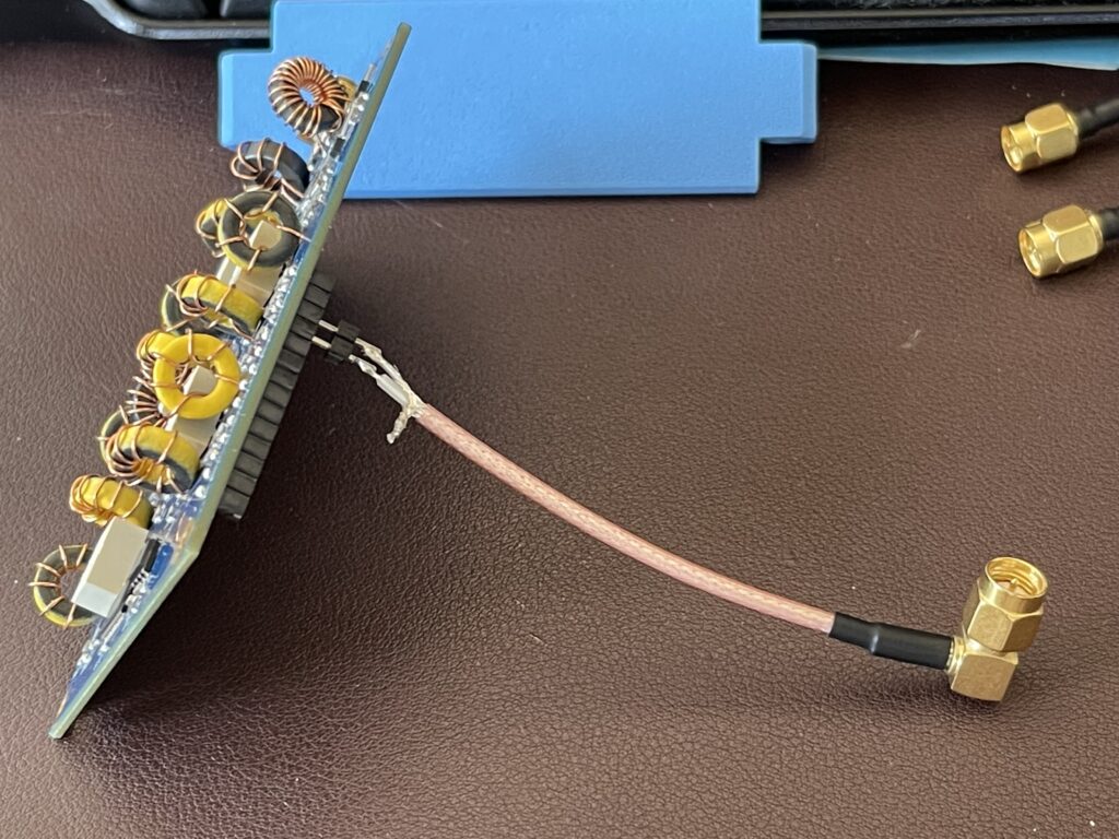
I used a spare SMA connector with coax attached and soldered a 2-pin header to the other end. The 2-pin header was then plugged into the RF input and GND location on the header socket.
The (tr)uSDX uses 5 relays to switch in the appropriate low pass filter based on the band selected in the menu. Those relays stay in position after power is removed from the RF board – this means you can select a band, then remove power and the main board from the RF board and test the filter for that band. This process needs to be repeated in order to test each band.
I tested the 10 meter band first, as this is the widest band for this kit. The 10 meter band allocation is from 28.000 MHz through 29.700 MHz. This means the second harmonic would be in the range of 56 MHz to approximately 60 MHz. The low pass filter for 10 meters should provide the maximum attenuation around the middle of the second harmonic, which is about 58 MHz. This would provide the maximum attenuation between 56 MHz and 60 MHz.
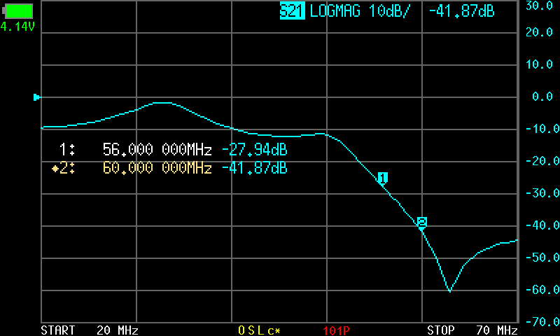
The initial sweep with the nanoVNA indicated that I had only a 28dB drop on the low end of the 10 meter band. Assuming I am outputting less than 5 watts of power on 10 meters, this does not quite offer the required 30dB attenuation from the fundamental frequency.
On the nanoVNA, I used a sweep from 20 MHz to 70 Mhz, then I added 2 markers to measure the attenuation level at 56 MHz and 60 MHz. From the screen shot above, marker 1 (56 MHz) indicates only a 27.94dB drop, and marker 2 (60MHz) indicates a 41.87dB drop. You can see from the image above that the dip is too far to the right (frequency is shifted up higher from where it needs to be).
In order bring this into FCC compliance, I need to have at least a 30dB attenuation at the second harmonic, or, if over 5 watts output power, at least a 40dB attenuation. I adjusted the windings of the toroids for the 10 meter band by moving them closer together, and the result was a shift of the dip to the left (in between where the markers are).
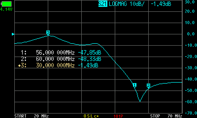
By changing the spacing on the toroid windings for the 10 meter section, I was able to bring the dip closer to the mid-point of the second harmonic of the 10 meter band allocation. Markers 1 and 2 (56 MHz and 60 MHz) now indicate adequate attenuation of the second harmonic. I added a third marker at the high point (basically zero dB suppression) to visually indicate that the filter has the lowest suppression near the end of the 10 meter band on the primary frequency output.
After adjustment, I now have at least a 40db attenuation on the 2nd harmonic, exceeding the FCC requirements of 30dB at less than 5 watts of output power, and 40dB for output higher than 5 watts.
When testing the 15 meter band, the toroid windings needed some adjustment as well:

The trace above indicates the dip is a bit too far to the right and needed to be moved to the left. The windings on these toroids were adjusted (closer together) and the result was a better match:

I repeated the procedure for the remaining 3 bands. I needed to make minor adjustments for the 17 meter and 20 meter bands as well.
Conclusion
The build of this kit went much faster for me as this was the second time putting one of these together. I will be testing the SSB modulation and FM modulation (on 10 meters) and updating this post as I make progress.
Currently I have observed the FM modulation is very low, and FM receive is not yet working. I will update this post once I have discovered the cause and/or a fix is discovered.
I would highly recommend to anyone who assembles any transmitter kit to verify the rig meets or exceeds FCC requirements regarding harmonics / spurious emissions. If you are purchasing a commercially made transceiver, in theory, it should have passed FCC inspection, and will be labelled as such. However, our license class allows us to build our own transmitters, and it is our responsibility to verify those FCC standards are met after assembly. We cannot and should not expect or rely on the designers of kits or retailers who sell the kits to verify these meet FCC requirements.
In the case of the (tr)uSDX, these kits exceed the FCC requirements when assembled and adjusted correctly. Further, the tools needed to perform the basic testing and verification are far less expensive than they would have been a decade or more ago. NanoVNAs, for example, have become quite affordable, and, can be used for many purposes.