
Kenwood TS-830S SDR Panadapter
One of the modern conveniences of today’s HF rigs is the waterfall or panadapter display of signals near your VFO point. For me, this is “new”, as my first HF rig was the Kenwood TS-530SP, which I enjoy using now that I have been able to get it on the air. HF rigs before this convenient feature was “standard” simply did not have this waterfall or panadapter display built-in. Some had accessories to accomplish this, often at expensive prices.
Back when I first bought the TS-530SP (from N1QQV sk), I would turn the VFO back and forth, searching out distant signals – pausing here and there to see who it was and where they were. New amateurs or those who get used to the panadapter in today’s rigs might forget what it was like without this helpful feature.
When I got back into the hobby, I purchased rhe “shack in the box” Yaesu FT-991A, and was introduced to the waterfall display. I remember thinking how easy this made finding signals from the noise as I spin the dial. Further, if I was listening to or having a QSO on a specific frequency, I can see adjacent signals right on the display. I could see in real-time if another station was close to my VFO frequency

Modern Tech for Old Rigs
One of the additional features the Kenwood TS-830S has over the Kenwood TS-530SP and other Kenwood hybrids is the IF 1 and IF 2 outputs. These outputs are two RCA connections on the back of the rig. The IF (intermediate frequency) outputs can be used to feed the antenna input of an SDR. More specifically, the IF 1 output is at 8.83 Mhz and has a wide bandwidth due to this IF being before subsequent stages in the receiver.

According to the owners manual, this output is buffered and intended for panadapter use. More specifically, the Kenwood SM-220 station monitor with the BS-8 module installed. If I find one of these at a decent price it might be worth experimenting with it. However, until then, I can use any inexpensive SDR which can receive well at 8.83 MHz (HF).


The BS-8 module is designed for an input of 8.83 MHz and will add a more logarithmic scale to the signals received, allowing for simultaneous display of weak and strong signals without having to adjust the RF attenuation. Incidentally, the BS-5 module would be for the Kenwood transceivers that operated with the 3.39 MHz IF. The same station monitor could be used with both families of transceivers by simply choosing the corresponding BS-5 or BS-8 module.
SDR
I am using the SDRplay RSPdx for HF and general coverage listening. This SDR is optimized for HF whereas some of the other less expensive SDRs are not excellent receivers on the lower HF bands, but geared more for VHF on up.

The SDRplay RSPdx has 3 antenna inputs for receiving which can be switched via software. Antenna inputs A&B are SMA, while antenna input C is a BNC input.
Because I am using antenna inputs A and B for HF and general coverage respectively, input C (the BNC connector) is what I used to connect to the IF 1 output on the TS-830S. I used a 50 ohm BNC to RCA cable readily available at Amazon.

In theory, if I connect the IF 1 output from the TS-830S to the input on the SDR, tune it to the IF frequency, I should see what the HF rig “sees” on it’s VFO.
Initial Testing
My initial test was on 20-meters. I tuned to the first strong QSO I found on the TS-830S and then tuned the SDR to 8.83 MHz. I had to dial back the RF gain on the RSPdx a bit, in order to get the S meter roughly similar in scale that the TS-830S indicated on its S meter. I then fine tuned the VFO on the SDR until I heard the same signal. On 20-meters, the VFO on the SDR matched the TS-830S at 8.8316 MHz. On 40-meters, the match was at 8.8287 MHz.
The IF output from the TS-830 is inverted due to “spectral inversion“, or when tapping off and viewing an IF output that is based on the difference between the local oscillator frequency and input the signal frequency. The effect of this is the waterfall will appear to be flipped, with the frequency decreasing from left to right (higher frequency on the left, lower on the right). We normally expect to see the frequency increase from left to right.
Since the output is inverted visually, it is also inverted audibly, or when trying to listen in on sideband. We have all heard what it sounds like when you select the incorrect upper or lower sideband option when tuning into an SSB signal. The same strange version was what I heard initially when listening to signals on the SDR from the IF output on the TS-830S.
On 20-meters, phone is upper sideband, but on the SDR, I needed to flip the mode to lower sideband. On 40-meters, phone is lower sideband, I needed to change the mode on the SDR to upper sideband.
In addition to the inverted waterfall display, inverted SSB output, I have to remember to turn the VFO in the opposite direction compared to a radio that has the waterfall built-in. If you look at the waterfall, the CW portion of the band is flipped and over to the right side, and the phone section is on the left side.
Since there is no CAT control on the TS-830S, there was no easy way to sync the VFO display on the Kenwood to the VFO display on the SDR. For example, if I see a strong signal near my VFO point, I cannot easily see what frequency that signal is at. I would simply have to remember the scale on the display and turn the dial toward that signal by that amount. As I do so, the frequency display on the SDR remains fixed, at or around 8.83 MHz.
Below is a short video clip of my experiment on 20-meters:
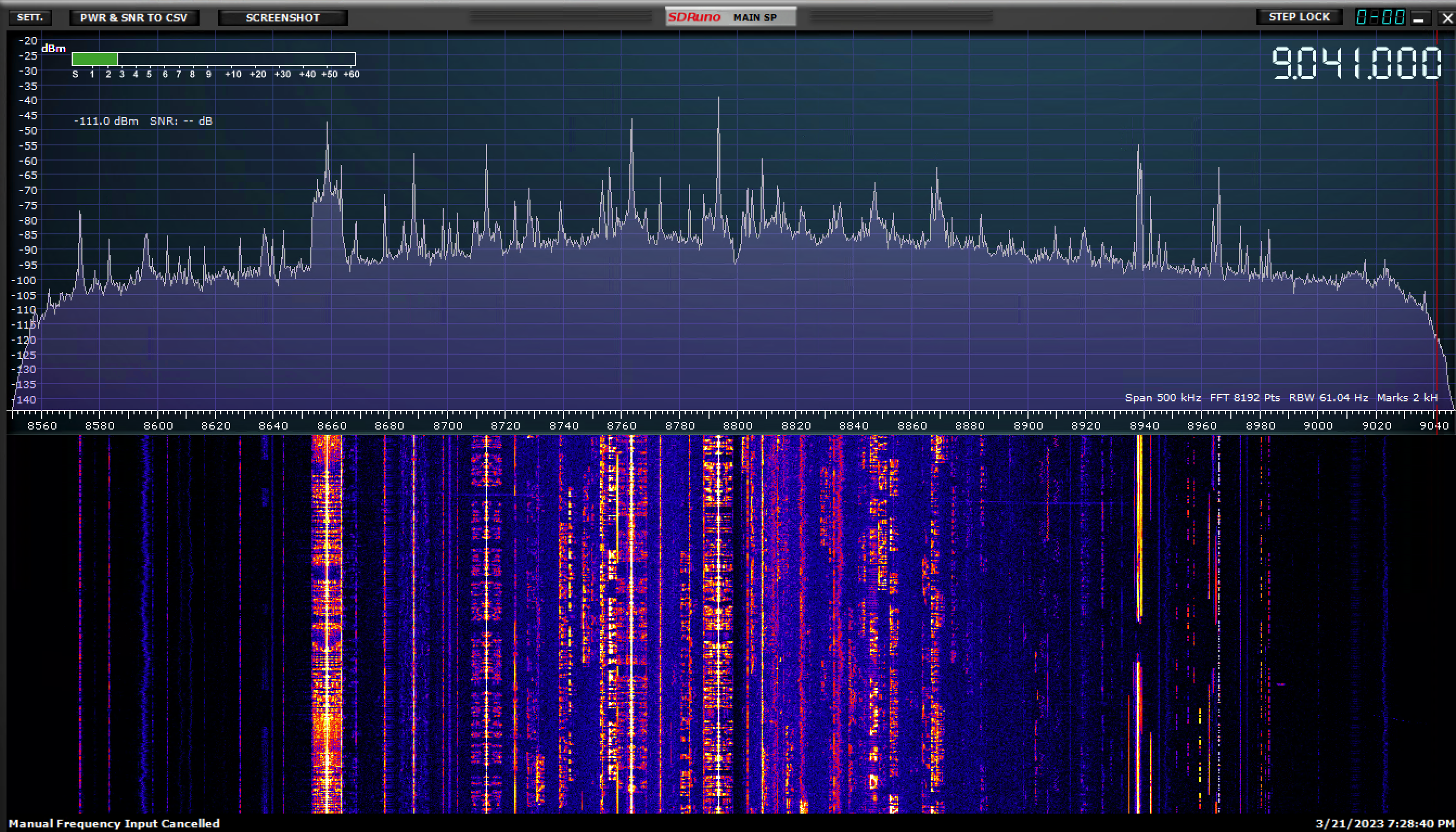
Below are snapshots of the waterfall on 20-meters and 40-meters in the early evening:


Closing Remarks
The limitations aside, it was useful to be able to see signals up and down the band from where the VFO is, for catching DX without having to spin the dial constantly back and forth.
What this panadapter method does allow for is an inexpensive way to add the waterfall feature to an old hybrid rig. Before I connected the SDR to the TS-830S, I would watch for DX on the SDR, then when I see the band activity I would switch the antenna over from the SDR to the TS-830S (using an antenna switch). This eliminates the need to keep switching antennas between the SDR and the TS-830S.
The resolution of the signals displayed on the SDR is much better than the Yaesu FT-991A, for example. Further, the bandwidth displayed on the SDR with the IF output from the TS-830S is about 360 KHz wide, from my observation. This is much wider than what the FT-991A displays at once. The SDR display is also better than the SM-220’s display resolution. However, the SM-220 allows for viewing of the modulated audio waveform being transmitted, which is helpful for detecting modulation issues such as clipping. Comparing a modern SDR to the SM-220 is not a fair comparison.
Update – SM-220
Since the original posting of this article, I found an SM-220 with the BS-8 module for a reasonable price.

I looked at the inside of the unit to make sure there was not anything living in there or components which were damaged or worn (visually). It passed the smoke test, and worked perfectly. Of course there may be issues with the capacitors or switches, but that can be easily fixed.

I connected the SM-220 to the IF input on the TS-830S and it worked quite well.
Besides a panadapter for receiving, the SM-220 can also be used to monitor the transmitted sideband audio signal from your transceiver. It does this by sampling the RF as it passes through the SM-220 RF in / RF out ports in the back. This can be helpful in determining if there is a problem with the ALC or clipping in modulation.

Further, the SM-220 can be used to monitor your amplifier for linearity.

The SM-220 can be used for much more than a panadapter and has some interesting features. W2AEW has a video which explains the SM-220 operation and is quite useful as an introduction: