


Power Distribution with Battery Backup
Powerpole Standard
Shortly after connecting my primary HF radio to my 13.8 volt power supply, I figured that I would need some way to add more than one device to the same supply. I settled on powerpole connectors as the means to connect every device to any power supply, including batteries. This allowed me to easily connect HTs, HF radios, mobile radios, TNCs, meters, and anything else that ran off 13.8 volts to a single powerpole distribution block.
Battery Backup
Shortly after sorting out and organizing the way I connect all 13.8 volt devices through a powerpole distribution block, I added a source of backup power. I did this right after a low power VHF contest last year when I learned that it was double points for contacts made while running on battery. It also made sense to have a means to power my equipment should main power go out.
I could have easily disconnected the main power supply from the powerpole distribution block and then plug in a battery in it’s place. However, that seemed to be a bit of a hack. I chose to wire in a battery switch to make it easier to manage the switching over from mains power to battery backup.
Charging the Battery
Of course, after running on battery power either for a short period or extended period, I would need to recharge the battery. I could recharge the battery from an AC LiFePO4 charger, or, from a solar charge controller. Since LiFePO4 batteries charge at a voltage a bit higher than 13.8 volts, I decided that I wanted a way to disconnect the battery and charger from the system completely during the recharge cycles. This required a second battery switch.
System Diagram
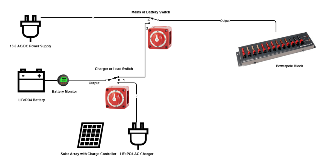
In order to figure out the best way to wire up the switches and various connections, I sketched out a drawing of the switches, battery, and other components of the system. I then used a free schematic designer to create the image above.
For operation on AC power, I would turn the “Mains or Battery” switch (top most switch in the picture above) to position 1. At this switch position, the battery section is not connected to the circuit.
For operation on battery power, I would turn the “Mains or Battery” switch to position 2. This disconnects the AC power supply from the circuit and connects the battery portion of the circuit. However, because I want to isolate the charging process from the circuit, the second battery switch “Charger or Load” switch must be on position 1. This leaves the charger disconnected from the circuit and only the battery connected.
For operation on AC power and simultaneous charging of the battery, the “Mains or Battery” switch would be on position 1 while the “Charger or Load” switch would be on position 2.
Note the battery monitor’s position in the circuit – it is located between the battery and the load or the charger at all times. This allows the monitor to indicate the level of charge remaining in the battery both when using the battery and when recharging the battery.
Battery Switches
The switches I used were the Blue Sea Systems 9001E switch which have 4 selectors (off, position 1, position 2, and position 1 + 2). I chose this switch because it can handle the amount of current needed and also because there always seems to be used ones available on Amazon or eBay.

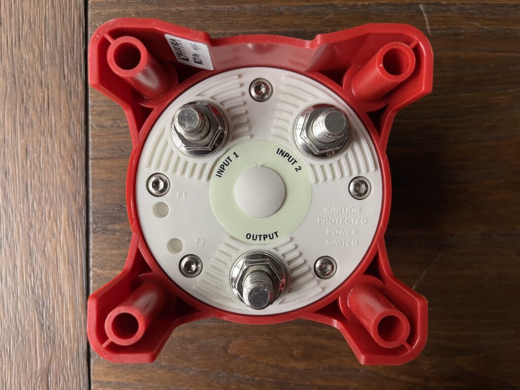
The switch has 3 connections on the back: Input 1, Input 2, and Output. When using these types of switches, the intent is to wire the positive side of the circuit through the switch, while using a common ground. The position of the switch in the off position results in none of the 3 positive terminals connected together. In position 1, the switch connects Input 1 to the Output. In position 2, the switch connects Input 2 to the Output. In the 1+2 position, all 3 are connected together. In my case, position 1+2 is never (and should not be) selected. Of course if the devices on the powerpole block can handle a bit over 14 volts DC, then in theory position 1+2 on the “Charger or Load” switch could be selected. This would allow for devices to be used while simultaneously charging the battery.
Connections
Batteries, chargers, and power supplies sometimes have screw terminals, PP45, or SB-120 connectors. In my case, I had to work with all 3 types of connections. This meant that I needed some SB-120, PP45 and ring connectors.
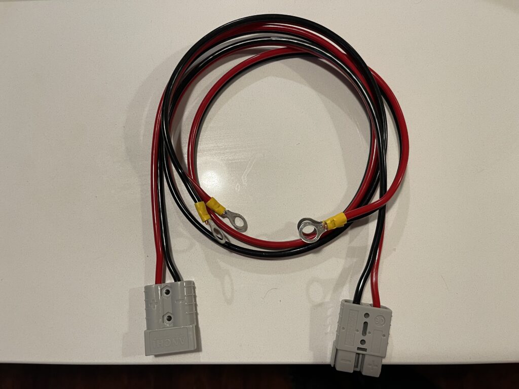
Before making any of the patch cords with various connectors, having the diagram of the system was very helpful. This allowed me to plan out how many of each type of crimp connector was needed and for making each section of patch cord.
I made all of the various connections with 10 AWG wire. In some cases I added some extra SB-120 connections where convenient for easy disconnecting. For example, the battery can be easily disconnected from it’s switch and taken portable. Or, I could swap out the battery for another one if needed.
Solar Charge Controller
When using a charge controller to recharge the LiFePO4 batteries, special consideration needs to be made in how the controller is connected to the system. Charge controllers need to be connected to the battery before being connected to the solar panel(s). This is to allow for the controller to power up and have the correct battery type selected before charging begins. In this design, I would add an additional switch that would disconnect the panel array from the charge controller. This would allow the controller to be connected to the battery first, then the array to the charge controller.
Closing Remarks
Having completed the wiring with the battery switches, I’ve tested out a few cycles running on battery backup and recharging. Being able to flip a few switches makes the process far easier than reaching for wires, disconnecting/reconnecting batteries and chargers.
One thing to note about the particular DC switches I used is there are some variations with covers for the back. This protects the connections (in my case the positive side of the supplies) from accidental short circuiting by coming into contact with a ground.
In my case I mounted each switch to a small block of wood so that there is a bit more protection from shorts.

I’ve also labeled each switch position so that they are clearly marked. Over time I found that I would forget which switch controls the charging and which switch controls the source.