
Radio Shack PC-2
There are quite a few interesting vintage computers and peripherals from the early 80s. One particular brand and product line I’ve had familiarity with are Tandy/Radio Shack “pocket computers”. These looked like larger scientific calculators to the passer-by. However, they really were computers in the sense that you can attach storage devices such as cassette recorders, printers, serial ports and more with some models. They were programmable with BASIC and sometimes assembly depending on the model.
History and Background
I did not have a real computer at home until the end of high school. It’s not that I’m that old – we couldn’t afford one. I vividly remember when, in 1st grade, new Apple computers were wheeled into the classroom. I quickly learned how to load games from 5.25” floppies and run them. Shortly after I learned BASIC programming and how to save and load my programs.
Before I got my first real computer, I had a Tandy PC-7 pocket computer for school and it also supported BASIC programming. It had a whopping 2 KB of RAM (1,568 bytes available for programs)! It did not support any peripherals, so saving and loading my programs was not possible. They had to be entered by hand. The calculator was relatively slow, and entering programs was kludgy.
At the time I wanted the PC-8 because it had a printer and cassette interface. However, they were hard to find and in demand compared to the PC-7. They were offered for only one year. The PC-7 on the other hand was sold for 3 years.
There were other pocket computer models around back then, all of which were out of my parents’ budget. A few decades later, after eBay is firmly established, I sought out a few of these models that were not affordable to us back then.
Radio Shack Pocket Computer Releases
The first pocket computer, the PC-1 was introduced for catalog year 1981 and the last catalog year for a pocket computer was 1992 with the PC-6. Interestingly, the PC-6 was the longest running model, from 1987 through 1992.

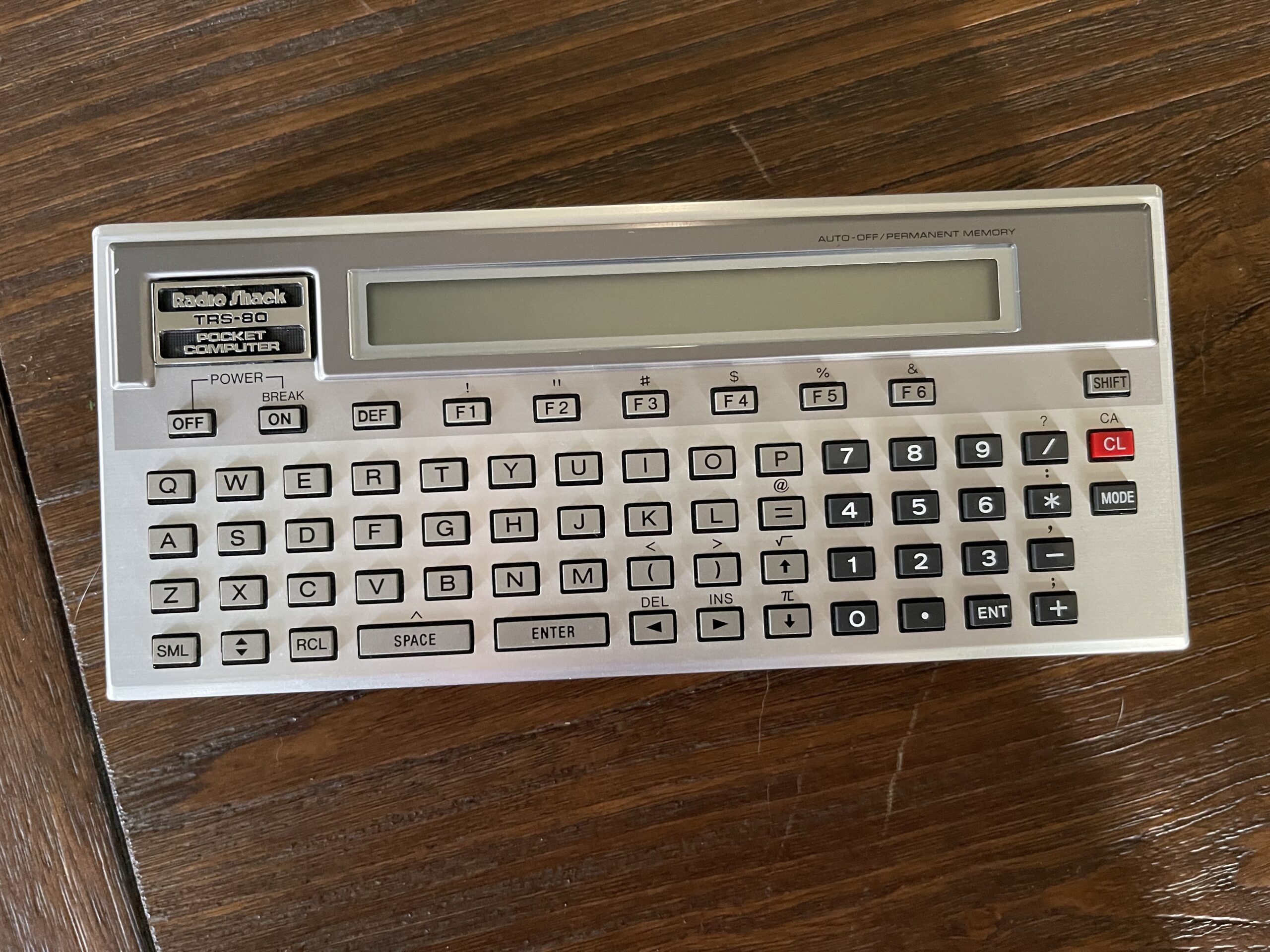
Radio Shack PC-2 / Sharp PC-1500
Years ago, I picked up a PC-2 in near perfect condition with the case (same as a Sharp PC-1500). I also found some PC-2 peripherals on eBay around the same time, when they were plentiful and fairly inexpensive (compared to today).


Why the PC-2? This model had the option of a 4-color printer/plotter, cassette, RS-232 module, and an expansion slot for RAM, ROM or other modules. Many of these models were used throughout various industries and had been in production long enough to have backward compatible revisions such as the PC-1500A for example.
The PC-2 has a 26 character LCD display which is dot addressable. This makes it possible for graphics and other screen effects. It has a buzzer which can be programmed for both pitch and duration. It has a real-time clock as well. The clock can be read and set using the TIME command in BASIC.
Similar to the PC-1, RadioShack sold software for the PC-2 in the form of cassettes. Titles included financial software, engineering software and games.
Its predecessor, the PC-1 was plagued by LCD screen leakage. Eventually every once of the LCDs went bad, and few were repaired. Many of the pocket computer models released after the PC-2 were less capable than the PC-2 in many ways. For example, many had slower processors, limited to no expansion capability, less RAM, or smaller keyboards. In fact, the PC-2 is very unique among all of the models of pocket computers Radio Shack would sell afterwards. None came close to the capabilities of the PC-2.
The PC-2 used 4 AA batteries, unlike the PC-1 and all other pocket computer models that used button cell batteries. It’s far easier to change AA batteries than it is to change button cells underneath a cover held on with tiny screws.
The PC-2 and peripherals sat in a box for many years until recently when I opened them up to see if they still worked.


The PC-2 came with 2 KB of RAM built-in. This provided 1,850 bytes available after a reset. With the 8 KB RAM module added, the available memory is 10,042 KB after a reset.


The price for the 8 KB RAM module was $139.95. That is quite an expensive upgrade at the time. The module had a cartridge style connector and tabs on the plastic case to ensure it was oriented correctly. Radio shack offered a 4 KB version of the expansion pack, and mentioned in the user guide up to 16 KB was possible for memory space (RAM or ROM). However, Radio Shack never offered anything greater than the 8 KB expansion. Sharp eventually released a 16 KB memory expansion module (for the PC-1500).
Instruction Manuals
It seemed as if the PC-2 had been rushed to market and became available in Radio Shack stores in early 1982. The instruction manual came with an insert which mentioned the TRS-80 PC-2 Programming Guide which was not available at the time the PC-2 was released. It was noted that the additional programming guide would be available in the summer of 1982.


I was never able to find the title of the book or guide “TRS-80 PC-2 Programming Guide”, but I did find a copy of the “Getting Started on the PC-2” book:


This book was first printed in May 1983, quite a bit later than the summer of 1982. This manual is comparable to the owners manual that came with the TRS-80 Model 100.
Peripherals
The PC-2 had a printer/plotter with cassette interface and an RS-232C interface as peripherals that can be attached to it’s 60-pin bus interface. The architecture of this interface and the memory bus allowed for peripherals to provide additional BASIC commands for the device being connected. For example, when connecting the RS-232C interface, more BASIC commands are available for sending and receiving characters, and a complete terminal program becomes available.
RS-232C Interface
The PC-2 had an RS-232 interface which operated between 50 and 2400 baud. It connected either directly to the PC-2 expansion bus or to the back of the printer/cassette module. This allowed the RS-232 interface to either be plugged in by itself to the PC-2 or in addition to the printer/cassette connected to the PC-2.

I was lucky to have grabbed one of these on eBay when it popped up awhile ago. Unfortunately it did not include anything except the module itself. There was no DC power adapter, mounting plate, nor any of the other items which came with the module.
No Service Manual
Almost all Radio Shack products have a service manual available, except this module. Therefore, creative methods for finding some specifications were needed.
Missing Battery Pack
This module, like the printer/cassette module, had an internal Ni-Cd battery pack. Anything this old would surely leak eventually, and unless this pack is removed before it leaks, it’s likely to create a mess at best, and damage to the peripheral at worst.
In my case, I was lucky that the previous owner removed the pack at some point. This likely saved this vintage peripheral from almost certain demise.

With electronics this age, we must be careful to apply the correct voltage to the DC power input. With anything that had rechargeable batteries inside, the supply voltage was usually a bit higher. If you power the device without those batteries installed at the specified voltage, it could result in damage to the device. This is because the charging mechanism for the internal battery relied on that specific input voltage being higher, but also served as a voltage reducer or regulator. For example, with the printer, the 9 volt supply should only be used if the internal battery pack is present. Otherwise, a 6 volt supply should be used.
I didn’t want to take any chances with this module, so I chose to install a replacement battery pack.
The original pack was Ni-Cd AA x 4, 4.8 volts. These are quite common even today, except in NiMH variety. Most often you’ll see these in RC toys or larger devices which have replaceable packs.
I picked up an inexpensive pack on Amazon with a connector that fits well enough into the existing position of the original battery.

I ensured the polarity was correct by checking which pin had continuity to ground. Luckily this method worked, and I was able to slide the connector directly onto the header.
DC Adapter
Since I did not have the original DC adapter for this module, I needed to determine the input voltage. The user guide (available online) did not specify the input voltage. I was able to find a reference to the Sharp version of this module, the CE-158. The output voltage of the DC adapter is 8.2 volts at 350mA, center pin negative.

I picked up a variable DC adapter so that I can select 8.2 volts. Note that the barrel connection for DC power is center negative for this module as well as the PC-2. Having one of these variable DC adapters is useful for other devices as well.
Coincidentally, the power adapter for the PC-3 printer is 8.5 volts center negative. I could likely use this adapter as well, if needed.
Printer Plotter / Cassette Module
I had picked up a Sharp CE-150 from eBay around the same time I found the RS-232 module. This module has a 4 color plotter and is also the cassette interface. The CE-150 is the Sharp version of the printer and cassette module which is compatible with the PC-2. The Radio Shack version is not as commonly found.

Of all of the pocket computer printers Radio Shack sold, the PC-2 was the only one which was actually a 4-color plotter. This was the only pocket computer which could print graphics (vectors such as lines, curves, rotated text, etc). Every other printer for the other pocket computers would print text only and in left to right orientation only (not rotated).
The pen colors were black, red, green and blue. The paper size is 2 1/4” wide and is readily available these days.

It is interesting that Radio Shack labelled the plotter pens “Ink Cartridges”. The package above includes one of each: Red, Blue, Green. These same pens were used in Radio Shack’s CGP-115 plotter as well. Further, these are the same pens found in Atari, Commodore, Casio, and several other Alps-based plotters at the time.
I have since posted an article on how to refill these plotter pens. There were two iterations of these pens, the first were ball point tips (not easily refillable) and then at a later point these were replaced with roller ball style tips (easily refillable).
Unfortunately these printers, like the PC-1 and the PC-3 / PC-8 had an internal Ni-Cd battery pack, which by now has most likely leaked. The Ni-Cd pack needs to be replaced before the plotter is operational.
Replacing the Ni-Cd Battery Pack
My first replacement was performed on a Sharp CE-150, which is almost identical to the Radio Shack version.
If the internal battery pack is removed, the external DC supply voltage should be 6 volts and not the listed 9 volts with the original DC adapter. I replaced the battery pack so that I can use the original 9 volt DC power adapter which came with the CE-150. Further, I suspect the DC adapter which comes with this unit might not supply enough current for the plotter to operate. The additional current needed comes from the internal battery pack. This is why the pack should be replaced before operating the plotter.
I replaced the Ni-Cd battery pack with NiMH AA tabbed cells. I soldered the tabs together and shrink wrapped the pack together into the same shape as the original pack.


There is no room to spare in the CE-150 for a battery pack bigger than the original. This meant that the tape and shrink wrap used when building a replacement must be as thin as possible.
I soldered in the replacement battery pack and charged it up with the original AC adapter.
Note that the original Ni-Cd pack was rated at 500 mAh, while the NiMH replacement cells are rated at 2,000 mAh. That’s quite an upgrade!
Testing the Plotter Mechanism
The CE-150 powered up with the calculator and the plotter mechanism tried to move the pen holder but was unable to. It appears the plastic pinion gears on the stepper motors had cracked. There are 2 of these, one drives the paper feed roller (y-axis) and the other drives the pen mechanism (x-axis).


There are brass replacement pinion gears that are available here. Replacing the pinion gears involves modifying a 2” c-clamp so that you have a flat surface to push the pinion gear onto the stepper motor shaft. The back of c-clamp must be against the other end of the stepper motor shaft to prevent damage to the stepper motor.

Jeff Birt published a video on this replacement procedure.
In addition to the cracked pinion gears, the anti-backlash gear on the paper roller also had a nub break off, and the spring was dangling on the shaft. The hub had also cracked. This is somewhat reparable with a 3mm inside diameter hose clamp, but without the spring, there would be too much slack when the roller changed direction.
Cracked Gears

Rather than attempt a repair on this plotter mechanism, I swapped out this one for the original CE-150 I had which had the leaking battery damage. Since originally posting this article, I have since found a way to repair the broken anti-backlash gears when I repaired a Casio FA-10.
I powered up the calculator and the printer mechanism moved both the roller and the pens! A successful swap of the plotter mechanism completed the restoration.
Testing the Plotter
I loaded the Math Plotter program and gave it a go. It took about 13 minutes or so to print out a 3D plot of a sample function.
I had quite a few spare pens, most of which worked. A few had leaked a bit, while some of the others were completely dried out. However, I had enough pens to test out the plotter. I have since discovered a way to refill these plotter pens.

I was amazed to see this plotter mechanism still working, and with such precision for a rather simple design. What is impressive is only 2 stepper motors are needed, one to drive the paper roller up and down for the Y axis and another to move the pen holder back and forth for the X axis.


To switch pens, the software moves the pen holder all the way to the left where a pin rotates the holder clockwise. It knows which color is black due to a magnet switch and rotation to known state upon startup.
To push the pen to the paper, an electromagnet energizes to swing a plate forward pushing on the back of the pen at the top of the holder.
This plotter mechanism by Alps was used on many different plotters. This included brands such as Atari, Comodore, Sharp, Radio Shack / Tandy, and many others. Other models had wider carriages and paper for larger prints.
Radio Shack Printer Plotter
After I had gotten the Sharp printer plotter working, I found the Radio Shack version to match the PC-2 I had. It was in great condition, and even included the soft case. However, it too needed a battery pack replacement.

The Ni-Cd pack was not yet leaking, and the replacement was the same procedure as the Sharp version.


In addition to changing out the battery pack, I needed to do some repairs on the Alps plotter mechanism. I admittedly had to purchase several inexpensive “parts only” mechanisms because of the cracked nub on the anti-backlash gear. Replacing the pinion gears is simple. After a few attempts at finding a workable mechanism, I finally found one that had a working anti-backlash gear.
I pressed new pinion gears into the stepper motors and had a working unit! I’m glad to have found a Radio Shack version in such good condition otherwise, making the repair worth while.
Testing the RS-232 Interface
I connected the RS-232 interface, set the communication mode to 2400, 8, N, 1 and started the terminal program (which is in the ROM in the RS-232 interface). I connected the 25 pin serial port to the PC and opened a terminal connection using PuTTY. I was able to type on either the PC or the PC-2 and see the serial communication working both ways.
I then connected the serial port to a Kantronics KPC-3 TNC and tuned to the APRS frequency for 2-meters 144.390 MHz. I was able to see some of the APRS traffic on the PC-2 display. Since there is quite a bit of APRS traffic where I am, and due to the single line screen on the PC-2, It was difficult to follow the traffic.
I enabled the print spooler feature of the terminal program to see if it would work, and it did! The APRS traffic was routed to the plotter.

Even though the serial port interface is limited to a maximum of 2400 baud, the KPC-3 can match that interface rate. It would be possible to use the PC-2 to interact with TNC mailboxes, BBSes, and even “chat” mode through the KPC-3.
Commercial Software
You can still find quite a bit of the commercial software on archive.org, including relevant books for the PC-2:
https://archive.org/search?query=PC-2+Pocket+computer
Owners Manual and Service Manual
The owners manual for the PC-2 is included below:
The owners manual for the RS-232 interface is below:
The service manual for the PC-2 (including the printer) is included below:
Final Thoughts
Restoring the plotter and RS-232 modules and seeing them still working after 40 years was amazing. I always wanted one of these back in the late 80s and now I was able to play around with one.


Even though there isn’t really a purpose or use for one of these computers today, having one fully working and seeing how they worked is a reminder of how far things have come in terms of technology.
The PC-2 is also a great platform to learn microprocessors and design of software, ROM, RAM, and external bus interfaces.
Even though the cassette interface can be used to load and save programs to cassette tapes, it’s easier to use a PC and utilities that convert ASCII files to and from WAV files for the PC-2 / PC-1500.
I plan to experiment with some assembly level programming on this platform. I have some ideas for useful apps, and I have extensive experience with machine level coding (assembly) in embedded systems. I’ll post related articles as I make progress with a few ideas for apps.