

Radio Shack PC-2 Pocket Computer
There are quite a few interesting vintage computers and peripherals from the early 80s. One particular brand and product line I have had familiarity with are Tandy/Radio Shack “pocket computers”. These looked like larger scientific calculators to the passer-by. However, they really were computers in the sense that you can attach storage devices such as cassette recorders, printers, serial ports and more with some models. They were programmable with BASIC and sometimes assembly depending on the model.
History and Background
I did not have a real computer at home until the end of high school. It is not that I am that old – we could not afford one. I vividly remember when, in 1st grade, new Apple computers were wheeled into the classroom. I quickly learned how to load games from 5.25” floppies and run them. Shortly after I learned BASIC programming and how to save and load my programs.
Before I got my first real computer, I had a Tandy PC-7 pocket computer for school and it also supported BASIC programming. It had a whopping 2 KB of RAM (1,568 bytes available for programs)! It did not support any peripherals, so saving and loading my programs was not possible. They had to be entered by hand. The calculator was relatively slow, and entering programs was kludgy.
At the time I wanted the PC-8 because it had a printer and cassette interface. However, they were hard to find and in demand compared to the PC-7. They were offered for only one year. The PC-7 on the other hand was sold for 3 years.
There were other pocket computer models around back then, all of which were out of my parents’ budget. A few decades later, after eBay is firmly established, I sought out a few of these models that were not affordable to us back then.
Radio Shack Pocket Computer Releases
The first pocket computer, the PC-1 was introduced for catalog year 1981 and the last catalog year for a pocket computer was 1992 with the PC-6. Interestingly, the PC-6 was the longest running model, from 1987 through 1992.
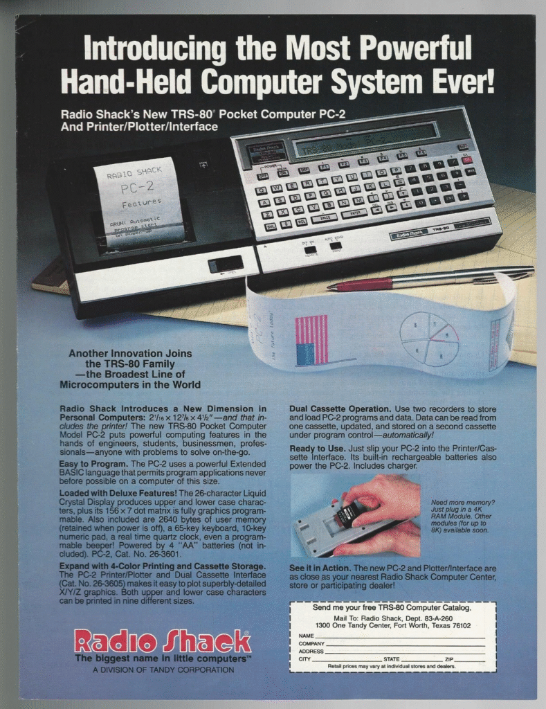
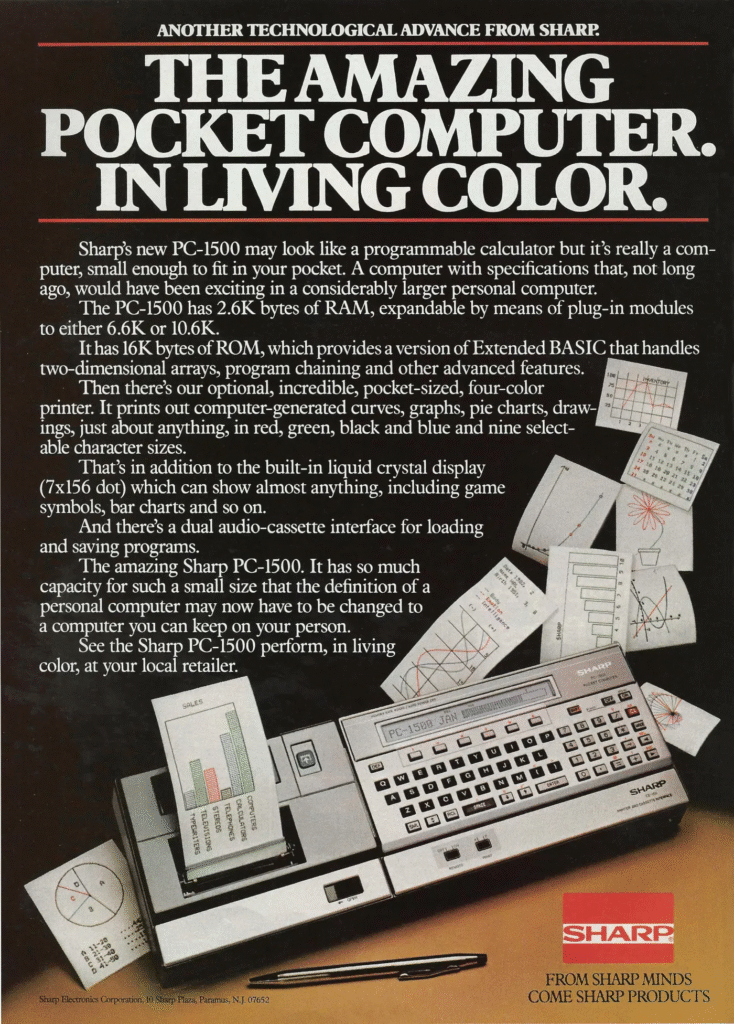
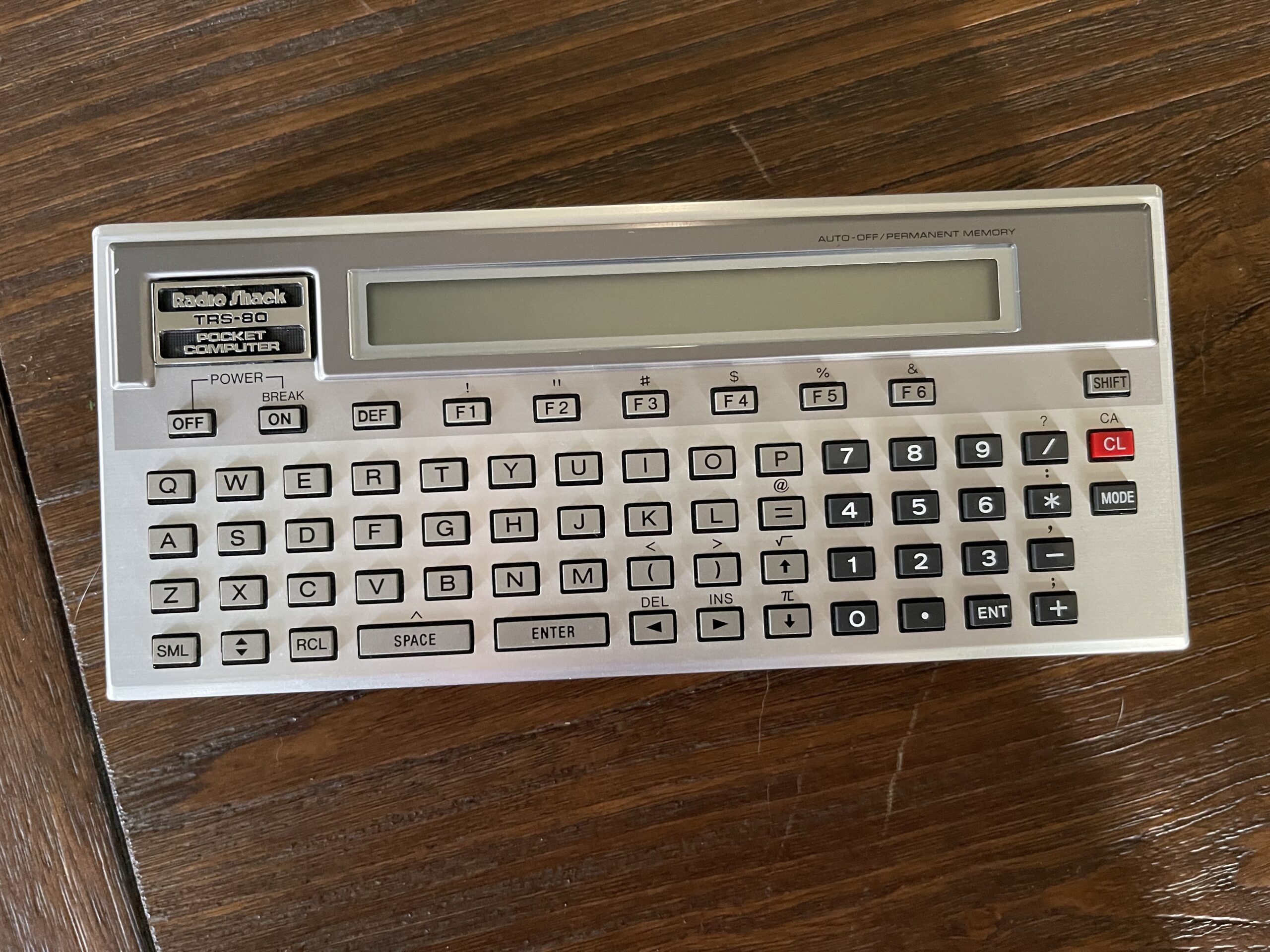
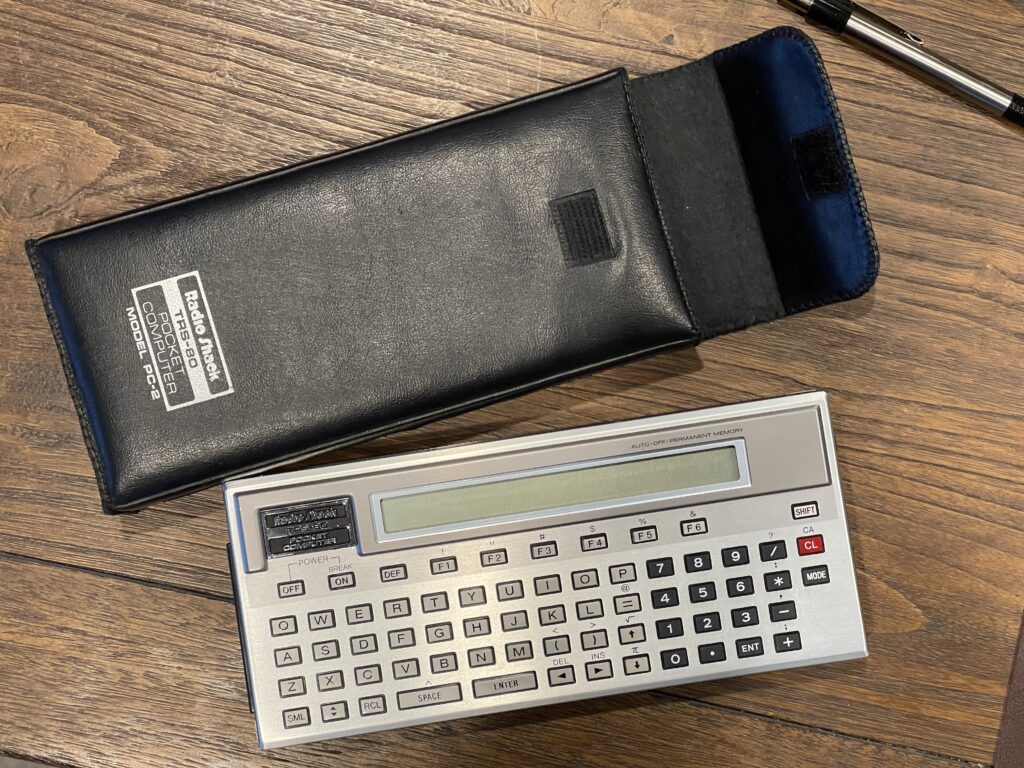
Radio Shack PC-2 / Sharp PC-1500
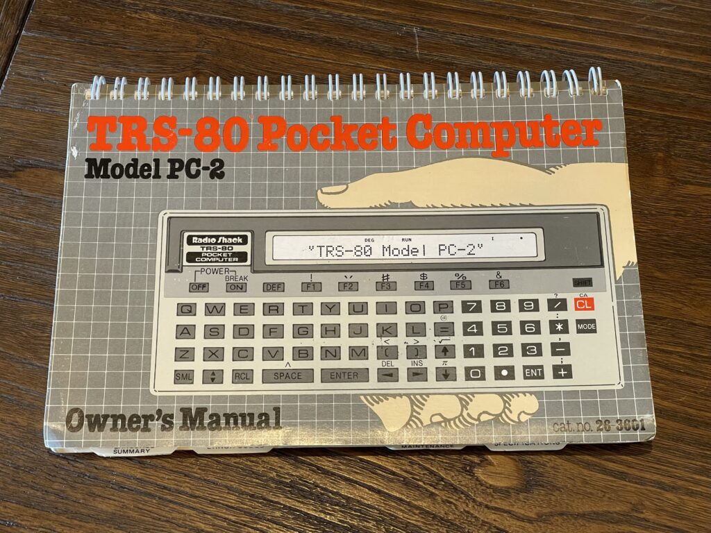
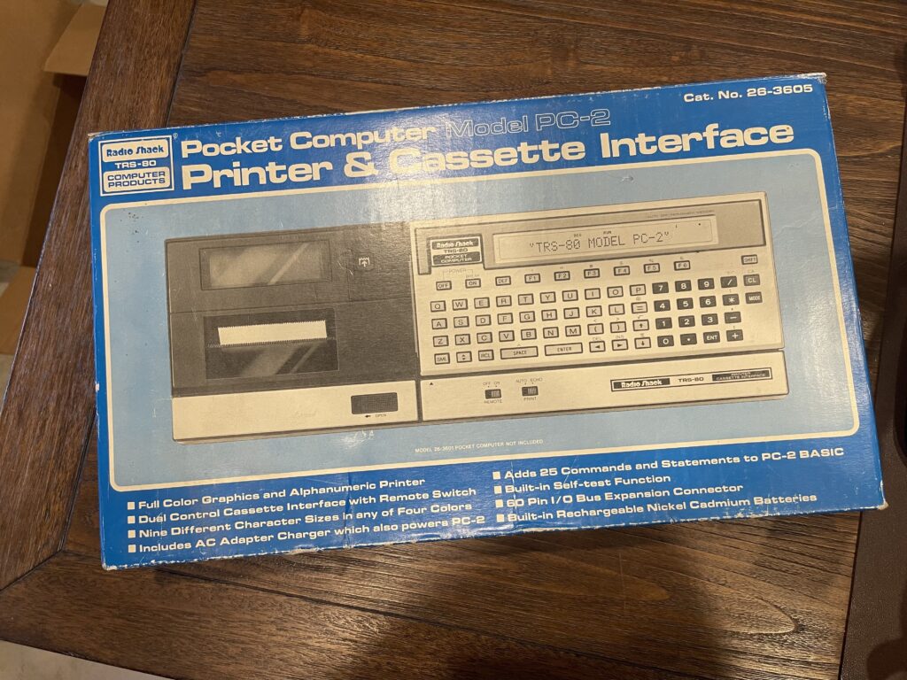
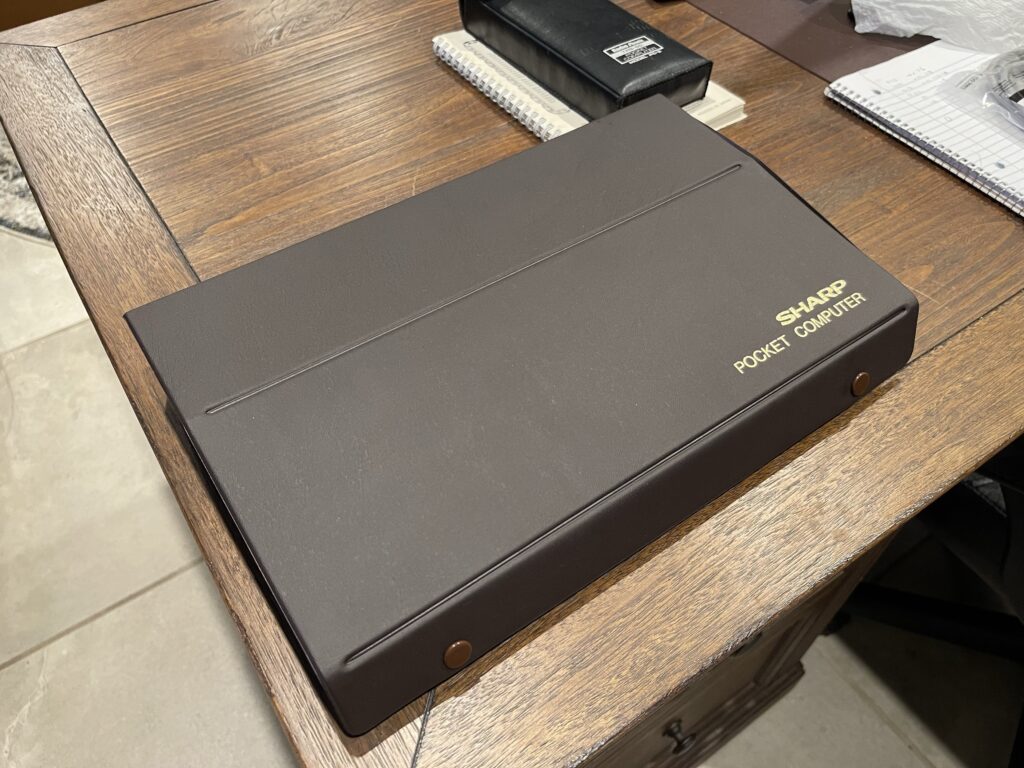
Years ago, I picked up a PC-2 in near perfect condition with the case (same as a Sharp PC-1500). I also found some PC-2 peripherals on eBay around the same time, when they were plentiful and fairly inexpensive (compared to today).

Why the PC-2? This model had the option of a 4-color printer/plotter, cassette, RS-232 module, and an expansion slot for RAM, ROM or other modules. Many of these models were used throughout various industries and had been in production long enough to have backward compatible revisions such as the PC-1500A for example.
The PC-2 has a 26 character LCD display which is dot addressable. This makes it possible for graphics and other screen effects. It has a buzzer which can be programmed for both pitch and duration. It has a real-time clock as well. The clock can be read and set using the TIME command in BASIC.
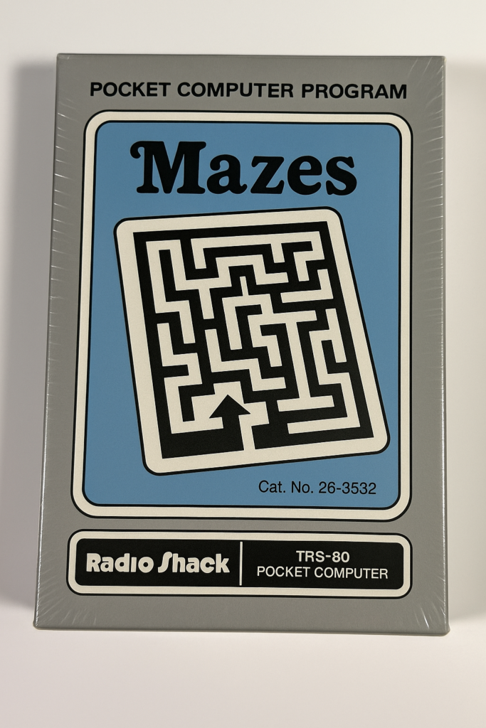
Similar to the PC-1, RadioShack sold software for the PC-2 in the form of cassettes. Titles included financial software, engineering software and games.
Its predecessor, the PC-1 was plagued by LCD screen leakage. Eventually every one of the LCDs went bad, and few were repaired. Many of the pocket computer models released after the PC-2 were less capable than the PC-2 in many ways. For example, many had slower processors, limited to no expansion capability, less RAM, or smaller keyboards. In fact, the PC-2 is very unique among all of the models of pocket computers Radio Shack would sell afterwards. None came close to the capabilities of the PC-2.
The PC-2 used 4 “AA” batteries, unlike the PC-1 and all other pocket computer models that used button cell batteries. It is far easier to change “AA” batteries than it is to change button cells underneath a cover held on with tiny screws.
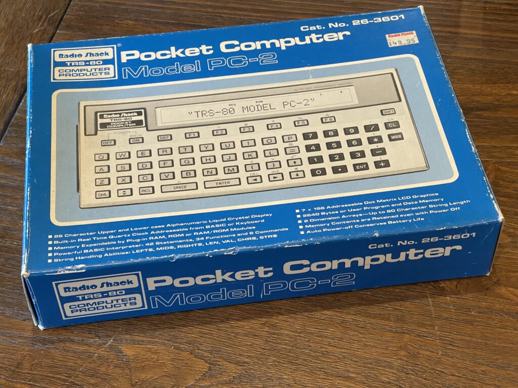
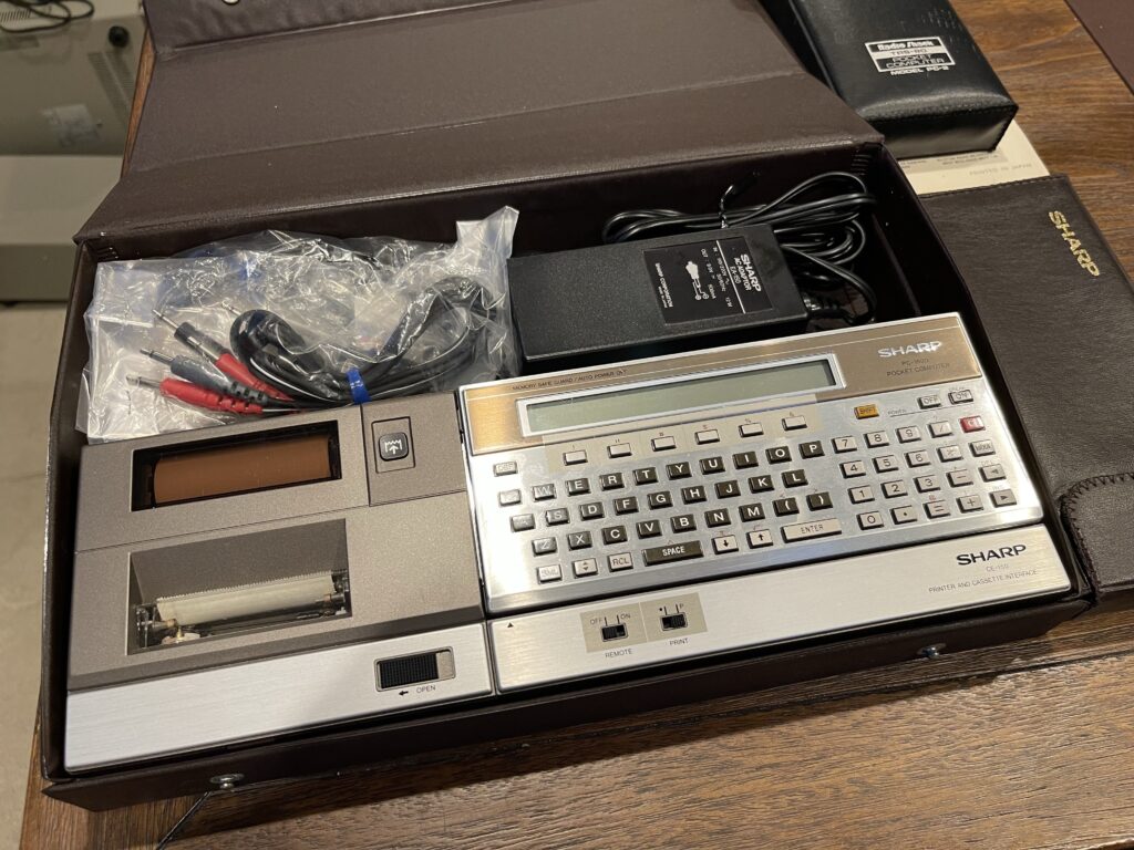
The PC-2 and peripherals sat in a box for many years until recently when I opened them up to see if they still worked.
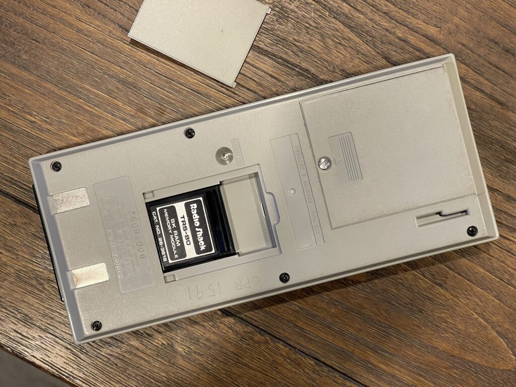
The PC-2 came with 2 KB of RAM built-in. This provided 1,850 bytes available after a reset. With the 8 KB RAM module added, the available memory is 10,042 KB after a reset.
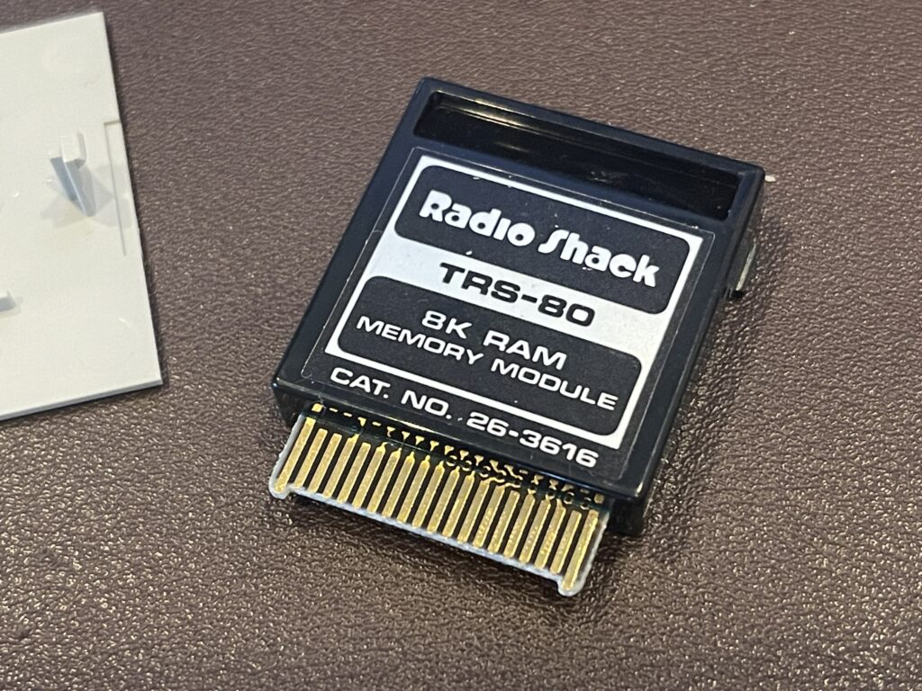
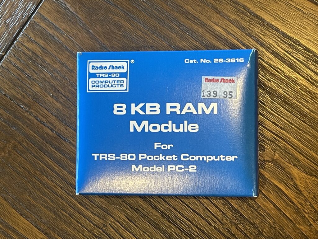
The price for the 8 KB RAM module was $139.95. That is quite an expensive upgrade at the time. The module had a cartridge style connector and tabs on the plastic case to ensure it was oriented correctly. Radio shack offered a 4 KB version of the expansion pack, and mentioned in the user guide up to 16 KB was possible for memory space (RAM or ROM). However, Radio Shack never offered anything greater than the 8 KB expansion. Sharp eventually released a 16 KB memory expansion module (for the PC-1500).
The model I acquired was purchased on October 20, 1983 at a Radio Shack in Woodbridge NJ, which is not too far from my current location.
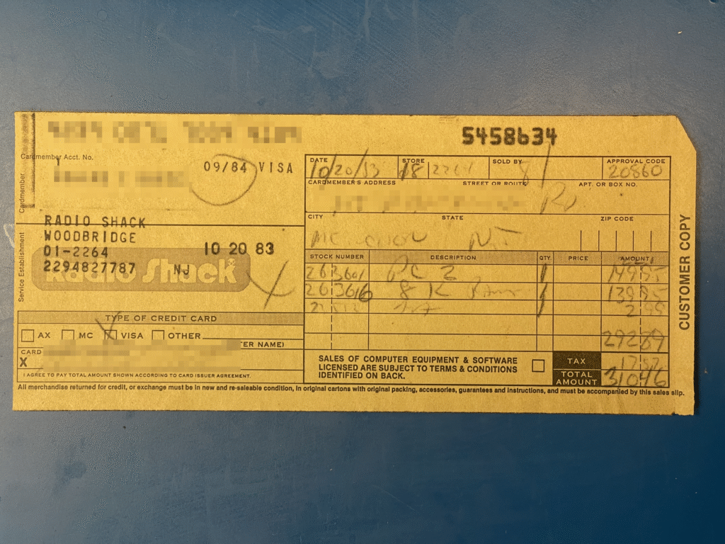
The purchaser had picked up the 8 KB expansion (at almost the same cost as the PC-2 itself) and a pack of “AA” batteries.
TRS-80 PC-2 versus Sharp PC-1500
Even though the TRS-80 PC-2 and the Sharp PC-1500 are functionally equivalent and compatible in terms of programs and peripherals, there is quite a bit of a cosmetic difference.
First, the keyboard layout is different. Placement of arrow keys, shift, on/off, mode, and many others are different. This leads to quite a bit of confusion if you are more familiar with one model and attempt to use the other model.
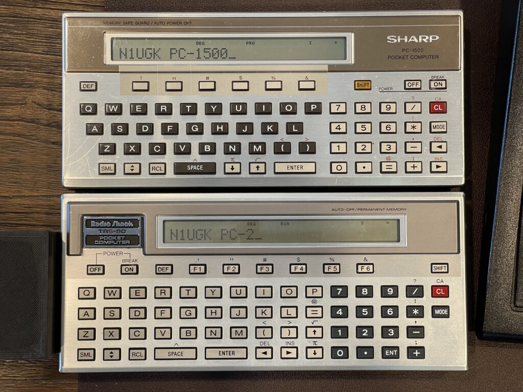
This is perhaps the only rebadged Radio Shack pocket computer which has a different keyboard layout than its brand name equivalent.
Minor Repair Needed
I recently took out my first PC-2 I had purchased on eBay more than a decade ago, and noticed the LCD was flickering a bit and some of the characters had extra pixels on. This did not seem like a stuck column or row exactly.
I cleaned the battery contacts as they had a very small amount of corrosion on them. I recharged my “AA” lithium ion batteries thinking they were slightly weak. The issue with the LCD persisted.
I took apart the PC-2 and noticed a stray strand of solder stuck to one of the pads on the LCD and keyboard half of the computer:
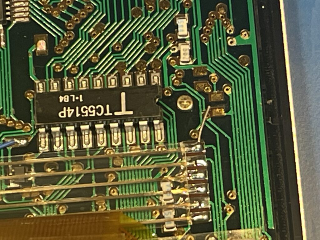
I did not have much hope that was the issue, since this PC-1 had worked perfectly for many years prior.
I removed the LCD itself and cleaned the PCB contacts, zebra strips and the pads on the LCD glass. I put the LCD back together and the issue persisted.
I was hoping it was not the flexible ribbon connectors between the two PCBs, as that is quite a difficult if not impossible repair.
I then pressed a bunch of keys on the keyboard, turned the unit off and on a bunch of times, reset the unit, and once or twice while pressing the “off” button, I saw a bunch of scrambled text on the screen and sometimes the “off” button resulted in a “Q” appearing on the LCD.
I then assumed there must be something wrong with the other side of the PCB where the keyboard traces and contacts are. I lifted up the rubber contact sheet for the keyboard and saw what appeared to be some liquid and decomposed solder mask:
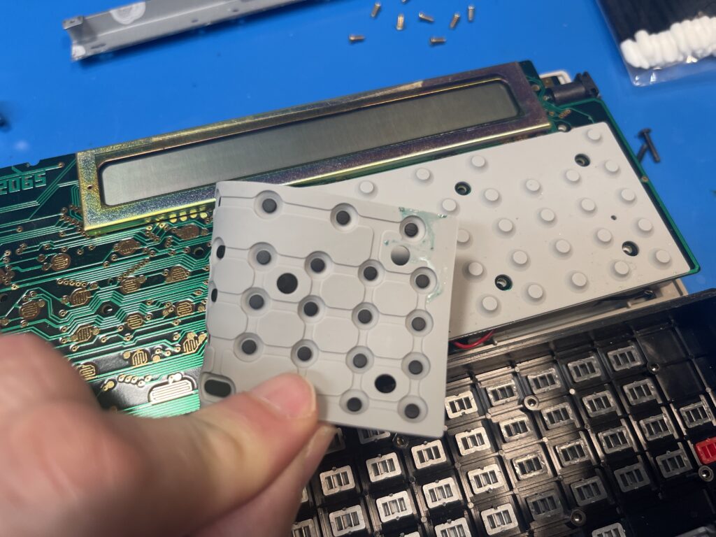
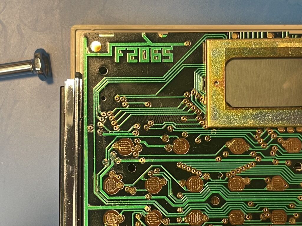
I cleaned up the liquid and used some vinegar to neutralize what I assume to be alkaline from leaking batteries. The corrosion did dissolve some of the solder mask, and, it would appear some of the traces impacted run up to the zebra strip terminal for the LCD.
After cleaning up the area with IPA the LCD worked again!
Instruction Manuals
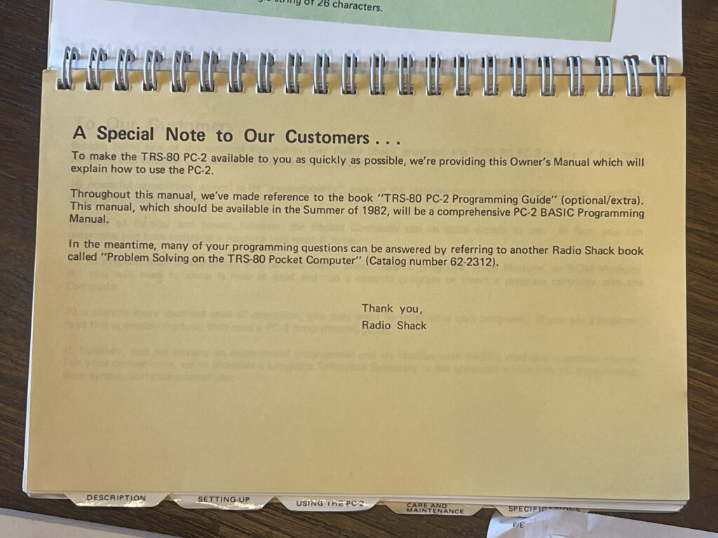
It seemed as if the PC-2 had been rushed to market and became available in Radio Shack stores in early 1982. The instruction manual came with an insert which mentioned the TRS-80 PC-2 Programming Guide which was not available at the time the PC-2 was released. It was noted that the additional programming guide would be available in the summer of 1982.
I was never able to find the title of the book or guide “TRS-80 PC-2 Programming Guide”, but I did find a copy of the “Getting Started on the PC-2” book:

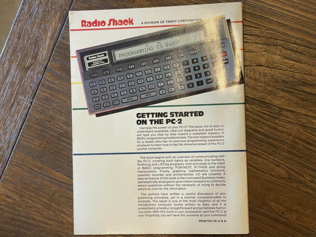
This book was first printed in May 1983, quite a bit later than the summer of 1982. This manual is comparable to the owners manual that came with the TRS-80 Model 100. The book is linked below:
The owners manual for the PC-2 is included below:
The owners manual for the RS-232 interface is below:
The service manual for the PC-2 (including the printer) is included below:
The Sharp version of the owner’s manual is below, for the PC-1500:
The Sharp PC-1500 Technical Reference Guide is below:
Peripherals
The PC-2 had a printer/plotter with cassette interface and an RS-232C interface as peripherals that can be attached to it’s 60-pin bus interface. The architecture of this interface and the memory bus allowed for peripherals to provide additional BASIC commands for the device being connected. For example, when connecting the RS-232C interface, more BASIC commands are available for sending and receiving characters, and a complete terminal program becomes available.
RS-232C Interface
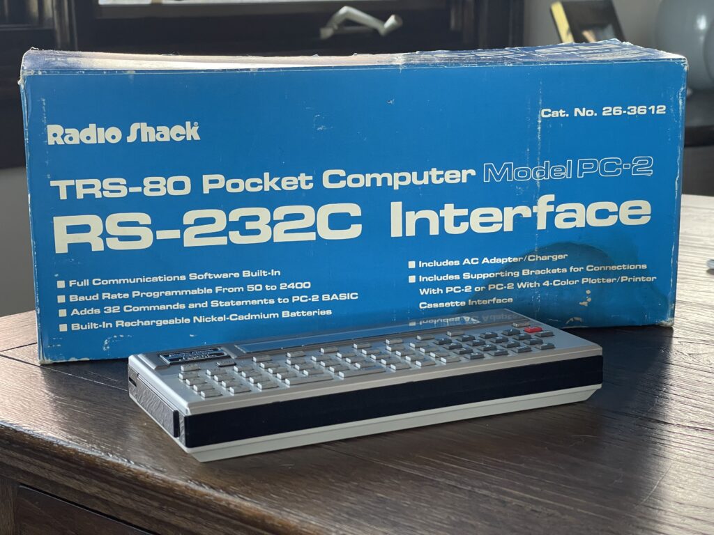
The PC-2 had an RS-232 interface which operated between 50 and 2400 baud. It connected either directly to the PC-2 expansion bus or to the back of the printer/cassette module. This allowed the RS-232 interface to either be plugged in by itself to the PC-2 or in addition to the printer/cassette connected to the PC-2.
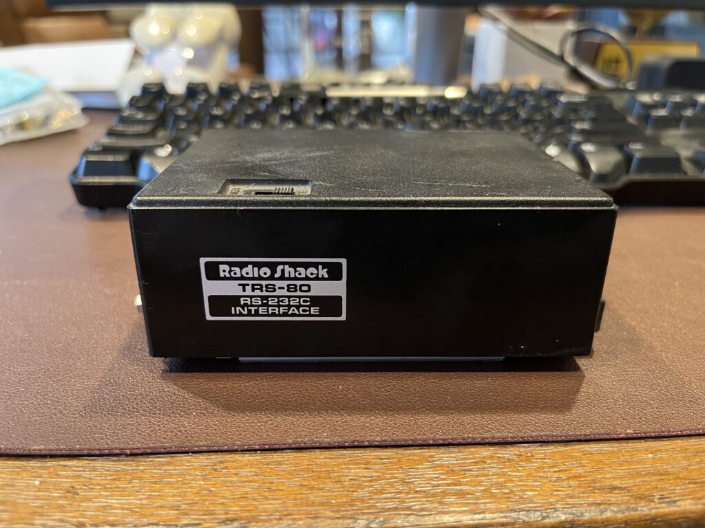
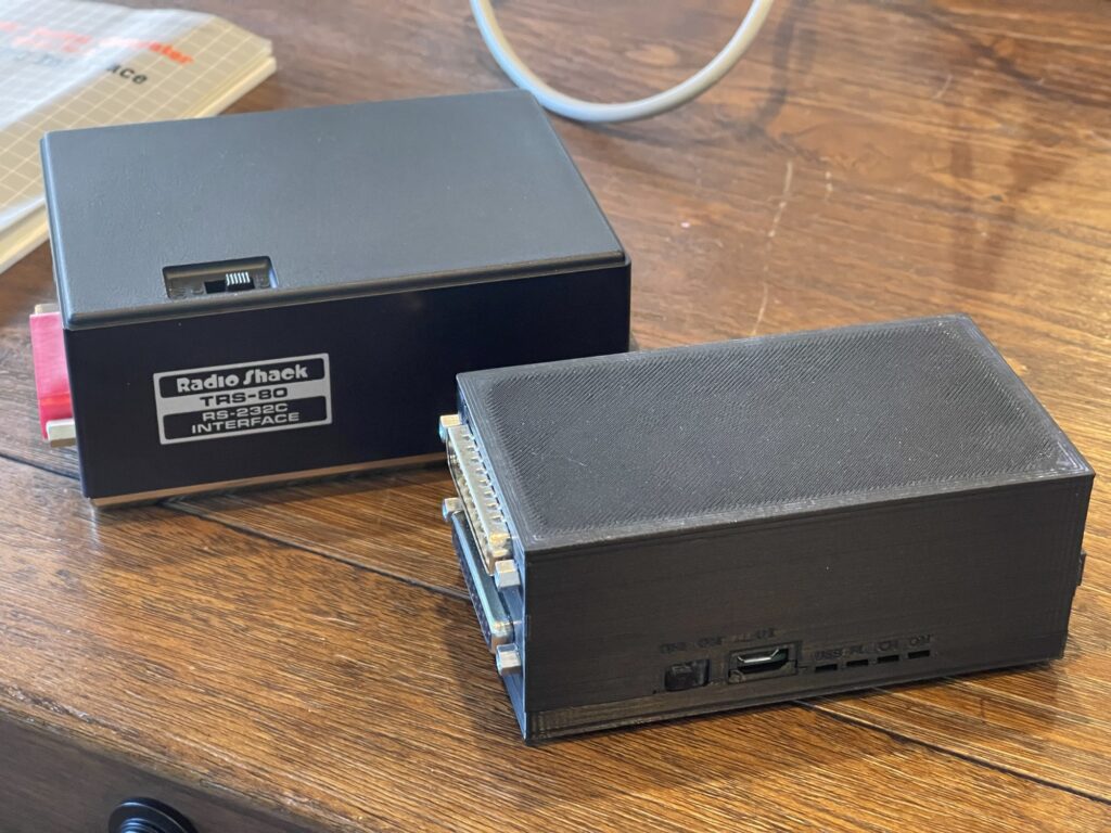
I was lucky to have grabbed one of these on eBay when it popped up awhile ago. Unfortunately it did not include anything except the module itself. There was no DC power adapter, mounting plate, nor any of the other items which came with the module.
No Service Manual
Almost all Radio Shack products have a service manual available, except this module. Therefore, creative methods for finding some specifications were needed.
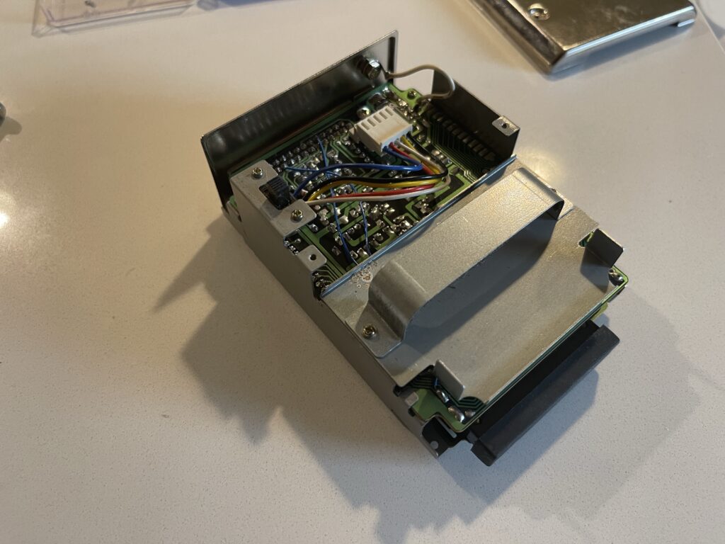
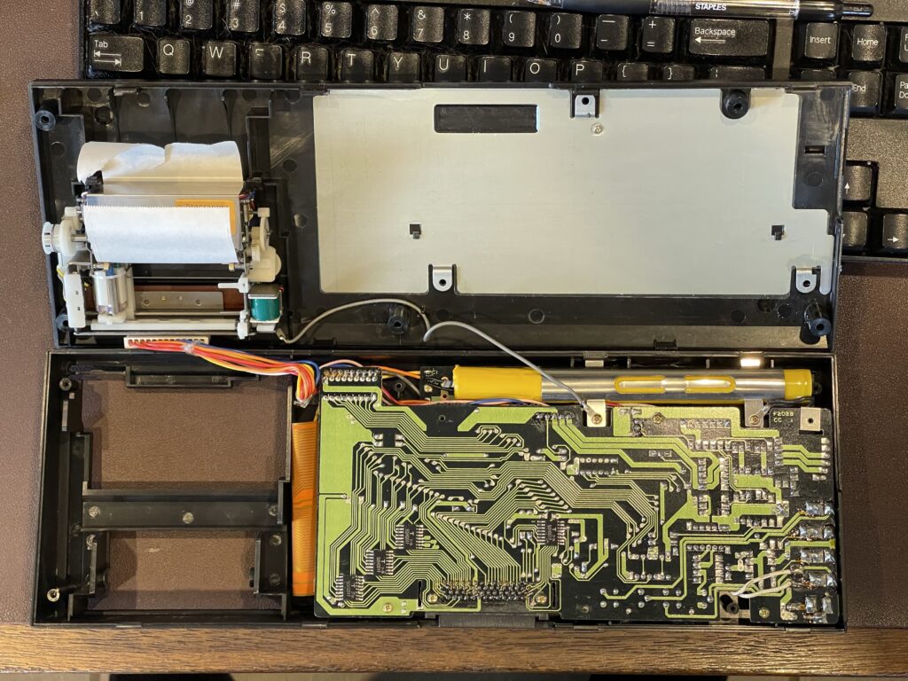
Missing Battery Pack
This module, like the printer/cassette module, had an internal NiCd battery pack. Anything this old would surely leak eventually, and unless this pack is removed before it leaks, it’s likely to create a mess at best, and damage to the peripheral at worst.
In my case, I was lucky that the previous owner removed the pack at some point. This likely saved this vintage peripheral from almost certain demise.
With electronics this age, we must be careful to apply the correct voltage to the DC power input. With anything that had rechargeable batteries inside, the supply voltage was usually a bit higher. If you power the device without those batteries installed at the specified voltage, it could result in damage to the device. This is because the charging mechanism for the internal battery relied on that specific input voltage being higher, but also served as a voltage reducer or regulator. For example, with the printer, the 9 volt supply should only be used if the internal battery pack is present. Otherwise, a 6 volt supply should be used.
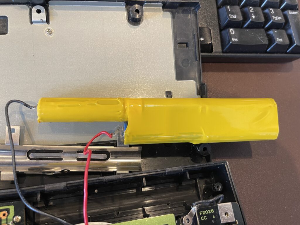
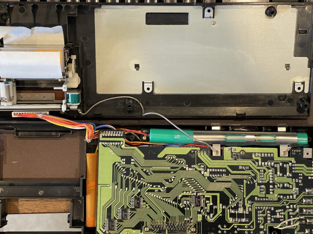
I didn’t want to take any chances with this module, so I chose to install a replacement battery pack.
The original pack was NiCd AA x 4, 4.8 volts. These are quite common even today, except in NiMH variety. Most often you’ll see these in RC toys or larger devices which have replaceable packs.
I picked up an inexpensive pack on Amazon with a connector that fits well enough into the existing position of the original battery.
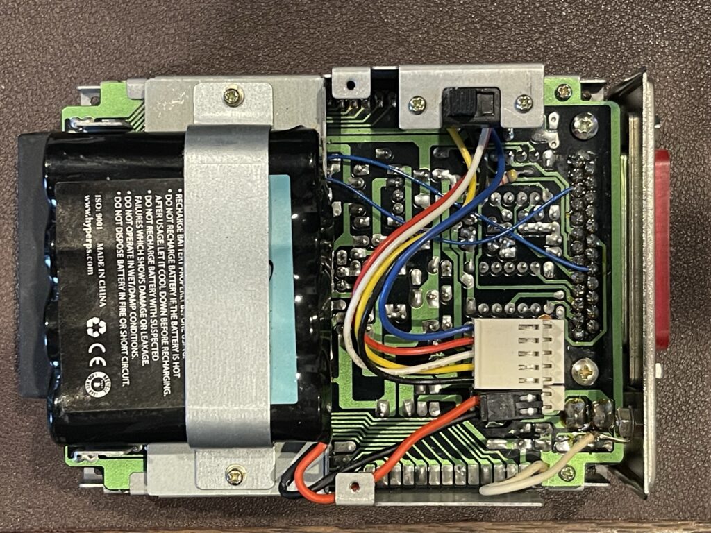
I ensured the polarity was correct by checking which pin had continuity to ground. Luckily this method worked, and I was able to slide the connector directly onto the header.
DC Adapter
Since I did not have the original DC adapter for this module, I needed to determine the input voltage. The user guide (available online) did not specify the input voltage. I was able to find a reference to the Sharp version of this module, the CE-158. The output voltage of the DC adapter is 8.2 volts at 350mA, center pin negative.
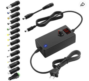
I picked up a variable DC adapter so that I can select 8.2 volts. Note that the barrel connection for DC power is center negative for this module as well as the PC-2. Having one of these variable DC adapters is useful for other devices as well.
Coincidentally, the power adapter for the PC-3 printer is 8.5 volts center negative. I could likely use this adapter as well, if needed.
Parallel Interface – CE-158
Sharp’s CE-158 module included not only the RS-232 interface, but it also had a parallel output port. These are difficult to find these days, and I myself do not have one.
This module would allow you to connect a standard parallel printer or plotter to the PC-2, for more printing options. Of course, there are plenty of serial printers available, but some vintage printers are only available with a parallel interface.
Note that pins 10 and 11 need to be swapped if connecting to an IBM PC compatible printer, or most vintage parallel printers not specifically designed for the Sharp 1500.
I have posted some more detail on usage of the RS-232 interface here.
The CE-158 owner’s manual is linked below for reference:
CE-158X
Jeff Birt has made available a new RS-232 and parallel interface for the PC-2 (and Sharp PC-1500). This interface is not only a functional replication of the original CE-158, but it also has some new features added, such as higher baud rates. This allows the PC-2 to be connected to serial devices higher than 2400 baud.
For me, this was a major enhancement to the PC-2, since I can now connect it to some amateur radio equipment and printers which operate at 9600 baud or higher. Below is a list of additional features and benefits of the CE-158X as seen from having only the Radio Shack RS-232 interface available:
- No NiCd nor NiMh packs to worry about, internal battery pack not needed
- Modern 18650 battery can be added if desired
- Can be powered from USB port
- Parallel port
- Input mode has been added on the parallel port
- Increased baud rate up to 38400 baud
- Second serial port on the USB side at 19200 baud
- “Dial-a-ROM” to select original ROM and other ROMS with enhancements
- Padded “feet” at the correct height for connection to the PC-2 (no metal mounting plates needed)
- BPD+ can be used to save/load programs
Jeff has posted a video walkthrough of this device here. Jeff mentioned in both the user guide for the CE-158X and the video on the CE-158X a firmware update for the BPD+ is forthcoming. The BPD+ is a neat device which connects to a serial port and emulates a disk drive. I purchased one of these for my Model 100. This would be a great addition for the PC-2 to be able to load and save programs and data using a BPD+, eliminating the need to use a PC.
Printer Plotter / Cassette Module
I had picked up a Sharp CE-150 from eBay around the same time I found the RS-232 module. This module has a 4 color plotter and is also the cassette interface. The CE-150 is the Sharp version of the printer and cassette module which is compatible with the PC-2. The Radio Shack version is not as commonly found.
Of all of the pocket computer printers Radio Shack sold, the PC-2 was the only one which was actually a 4-color plotter. This was the only pocket computer which could print graphics (vectors such as lines, curves, rotated text, etc). Every other printer for the other pocket computers would print text only and in left to right orientation only (not rotated).
The pen colors were black, red, green and blue. The paper size is 2 1/4” wide and is readily available these days.
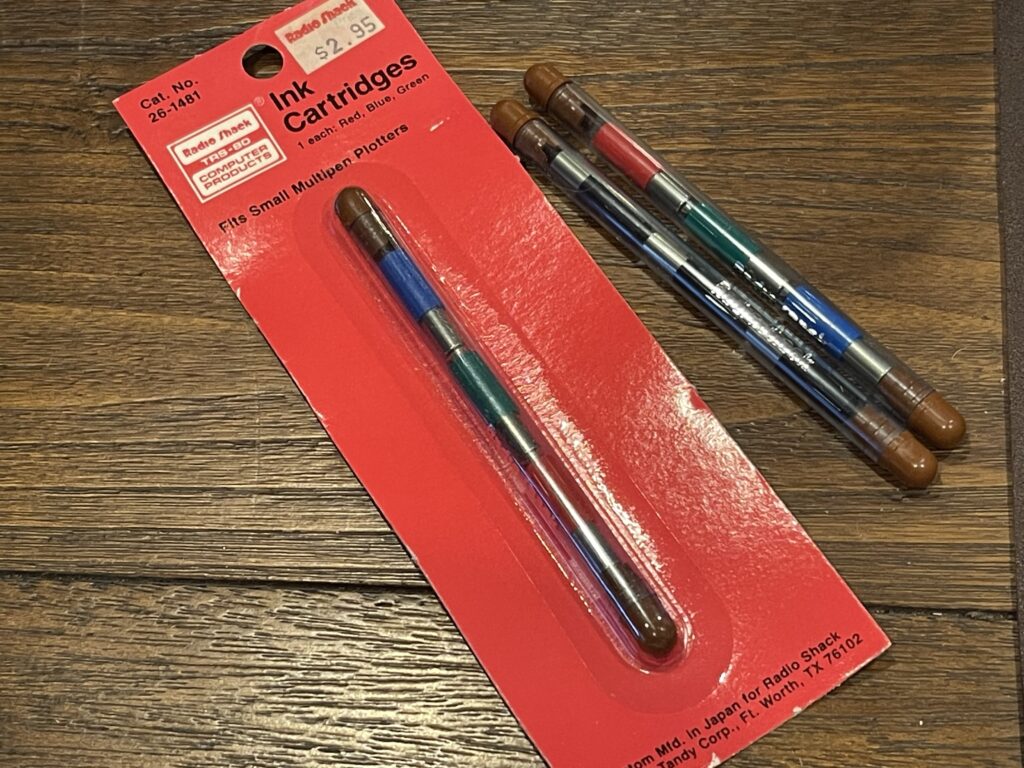
It is interesting that Radio Shack labelled the plotter pens “Ink Cartridges”. The package above includes one of each: Red, Blue, Green. These same pens were used in Radio Shack’s CGP-115 plotter as well. Further, these are the same pens found in Atari, Commodore, Casio, and several other Alps-based plotters at the time.
I have since posted an article on how to refill these plotter pens. There were two iterations of these pens, the first were ball point tips (not easily refillable) and then at a later point these were replaced with roller ball style tips (easily refillable).
Unfortunately these printers, like the PC-1 and the PC-3 / PC-8 had an internal NiCd battery pack, which by now has most likely leaked. The NiCd pack needs to be replaced before the plotter is operational.
Replacing the NiCd Battery Pack
My first replacement was performed on a Sharp CE-150, which is almost identical to the Radio Shack version.
If the internal battery pack is removed, the external DC supply voltage should be 6 volts and not the listed 9 volts with the original DC adapter. I replaced the battery pack so that I can use the original 9 volt DC power adapter which came with the CE-150. Further, I suspect the DC adapter which comes with this unit might not supply enough current for the plotter to operate. The additional current needed comes from the internal battery pack. This is why the pack should be replaced before operating the plotter.
I replaced the NiCd battery pack with NiMH AA tabbed cells. I soldered the tabs together and shrink wrapped the pack together into the same shape as the original pack.

There is no room to spare in the CE-150 for a battery pack bigger than the original. This meant that the tape and shrink wrap used when building a replacement must be as thin as possible.
I soldered in the replacement battery pack and charged it up with the original AC adapter.
Note that the original NiCd pack was rated at 500 mAh, while the NiMH replacement cells are rated at 2,000 mAh. That’s quite an upgrade!
Testing the Plotter Mechanism
The CE-150 powered up with the calculator and the plotter mechanism tried to move the pen holder but was unable to. It appears the plastic pinion gears on the stepper motors had cracked. There are 2 of these, one drives the paper feed roller (y-axis) and the other drives the pen mechanism (x-axis).
There are brass replacement pinion gears that are available here. Replacing the pinion gears involves modifying a 2” c-clamp so that you have a flat surface to push the pinion gear onto the stepper motor shaft. The back of c-clamp must be against the other end of the stepper motor shaft to prevent damage to the stepper motor.
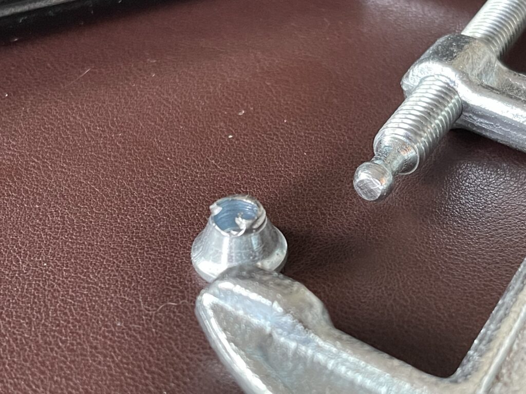
Jeff Birt published a video on this replacement procedure.
In addition to the cracked pinion gears, the anti-backlash gear on the paper roller also had a nub break off, and the spring was dangling on the shaft. The hub had also cracked. This is somewhat reparable with a 3mm inside diameter hose clamp, but without the spring, there would be too much slack when the roller changed direction.
Cracked Gears
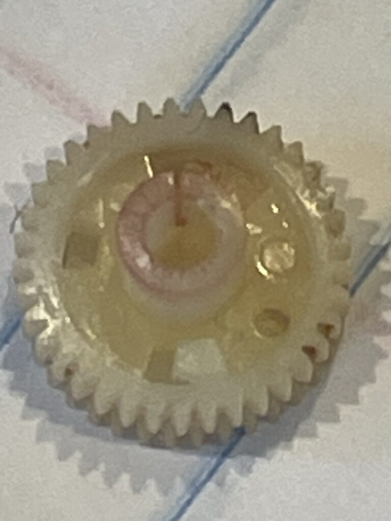
Rather than attempt a repair on this plotter mechanism, I swapped out this one for the original CE-150 I had which had the leaking battery damage. Since originally posting this article, I have since found a way to repair the broken anti-backlash gears when I repaired a Casio FA-10.
I powered up the calculator and the printer mechanism moved both the roller and the pens! A successful swap of the plotter mechanism completed the restoration.
Testing the Plotter
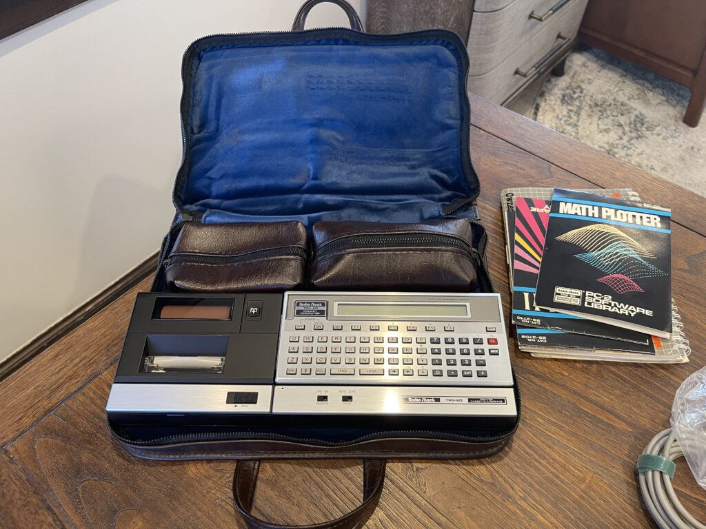
I loaded the Math Plotter program and gave it a go. It took about 13 minutes or so to print out a 3D plot of a sample function.
I had quite a few spare pens, most of which worked. A few had leaked a bit, while some of the others were completely dried out. However, I had enough pens to test out the plotter. I have since discovered a way to refill these plotter pens.
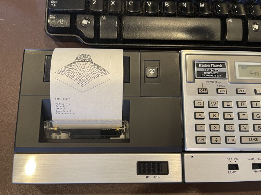
I was amazed to see this plotter mechanism still working, and with such precision for a rather simple design. What is impressive is only 2 stepper motors are needed, one to drive the paper roller up and down for the Y axis and another to move the pen holder back and forth for the X axis.
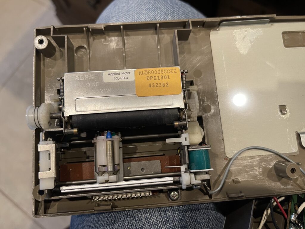
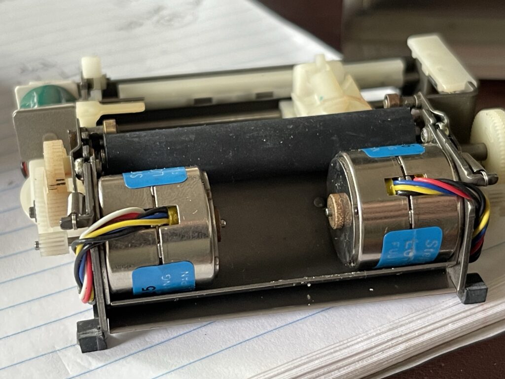
To switch pens, the software moves the pen holder all the way to the left where a pin rotates the holder clockwise. It knows which color is black due to a magnet switch and rotation to known state upon startup.
To push the pen to the paper, an electromagnet energizes to swing a plate forward pushing on the back of the pen at the top of the holder.
This plotter mechanism by Alps was used on many different plotters. This included brands such as Atari, Comodore, Sharp, Radio Shack / Tandy, and many others. Other models had wider carriages and paper for larger prints.
Radio Shack Printer Plotter
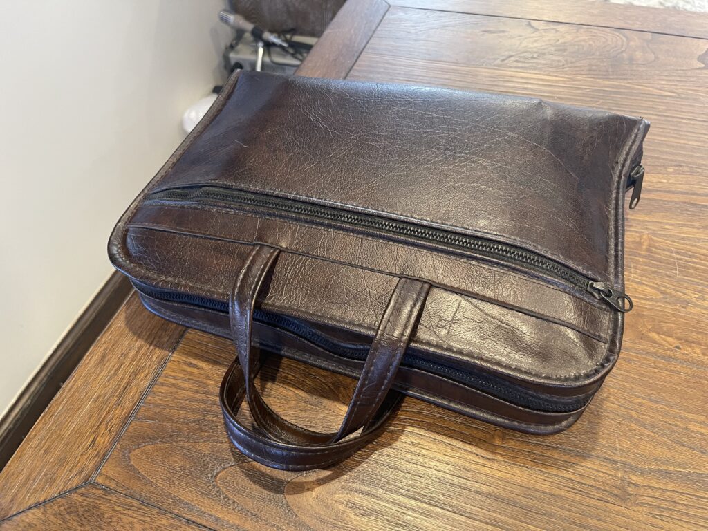
After I had gotten the Sharp printer plotter working, I found the Radio Shack version to match the PC-2 I had. It was in great condition, and even included the soft case. However, it too needed a battery pack replacement.
The NiCd pack was not yet leaking, and the replacement was the same procedure as the Sharp version.
In addition to changing out the battery pack, I needed to do some repairs on the Alps plotter mechanism. I admittedly had to purchase several inexpensive “parts only” mechanisms because of the cracked nub on the anti-backlash gear. Replacing the pinion gears is simple. After a few attempts at finding a workable mechanism, I finally found one that had a working anti-backlash gear.
I pressed new pinion gears into the stepper motors and had a working unit! I’m glad to have found a Radio Shack version in such good condition otherwise, making the repair worth while.
Testing the RS-232 Interface
I connected the RS-232 interface, set the communication mode to 2400, 8, N, 1 and started the terminal program (which is in the ROM in the RS-232 interface). I connected the 25 pin serial port to the PC and opened a terminal connection using PuTTY. I was able to type on either the PC or the PC-2 and see the serial communication working both ways.
I then connected the serial port to a Kantronics KPC-3 TNC and tuned to the APRS frequency for 2-meters 144.390 MHz. I was able to see some of the APRS traffic on the PC-2 display. Since there is quite a bit of APRS traffic where I am, and due to the single line screen on the PC-2, It was difficult to follow the traffic.
I enabled the print spooler feature of the terminal program to see if it would work, and it did! The APRS traffic was routed to the plotter.
Even though the serial port interface is limited to a maximum of 2400 baud, the KPC-3 can match that interface rate. It would be possible to use the PC-2 to interact with TNC mailboxes, BBSes, and even “chat” mode through the KPC-3.
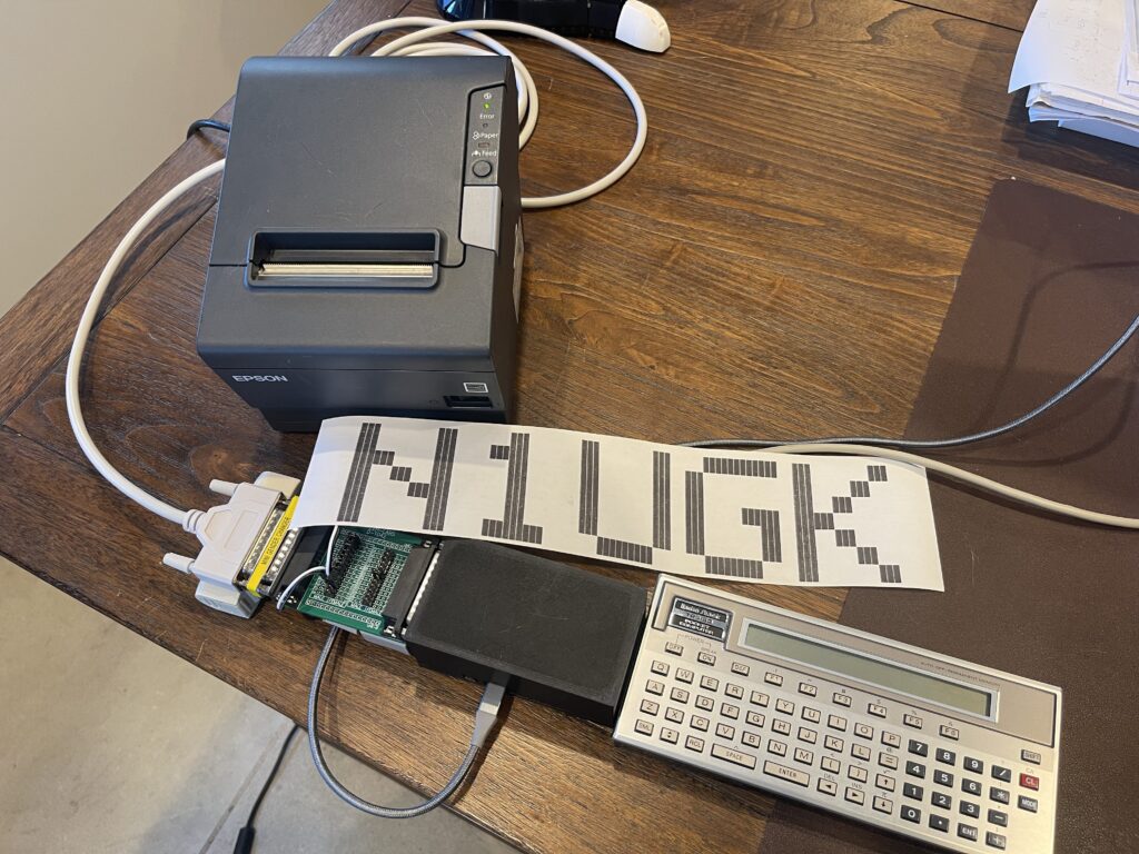
Banner Program
One way I become familiar with a pocket computer and its version of BASIC is to write a banner program. Since the PC-2 does not have a thermal or dot matrix printer, it has a plotter and printing banners on the plotter does not come out all that well. Since the plotter works with lines and small text, it would be wasteful and time consuming to print large solid letters on the plotter.
Since I have RS-232 and parallel ports available, I can print to a serial printer, such as the TP-10, or, any parallel printer, such as an Epson TM-T88V. I have written a banner program for the PC-2 and the TP-10 and posted it here.
The TP-10 is quite a slow thermal printer, and the Epson TM-T88V is far faster. Not to mention, thermal paper for POS printers is far cheaper and widely available.
My original version of the banner program was made for the PC-8, which used just over 900 bytes of RAM. In that version, I had to include the font bitmap data, as the undocumented PEEK command does not work with the ROM address space, only the 2KB RAM area.
The second version of the banner program I wrote was for the Model 100. In that version, I referenced the font bitmap data within the ROM of the Model 100. This version gave me all of the printable characters without any extra program space or effort to create the characters in a font bitmap.
Finding the Characters in ROM
In order to use the same method for the banner program for the PC-2 (as I did with the Model 100), I would need to know where and how the font bitmap data is stored within the system ROM. Similar to the Model 100 version, I searched the world wide web for a PC-1500 ROM dump with a mapping of the areas of the ROM. I did not want to spend too much time searching, and I did not find what I wanted.
I looked through the PC-1500 Technical Reference Manual, and spotted a memory map:
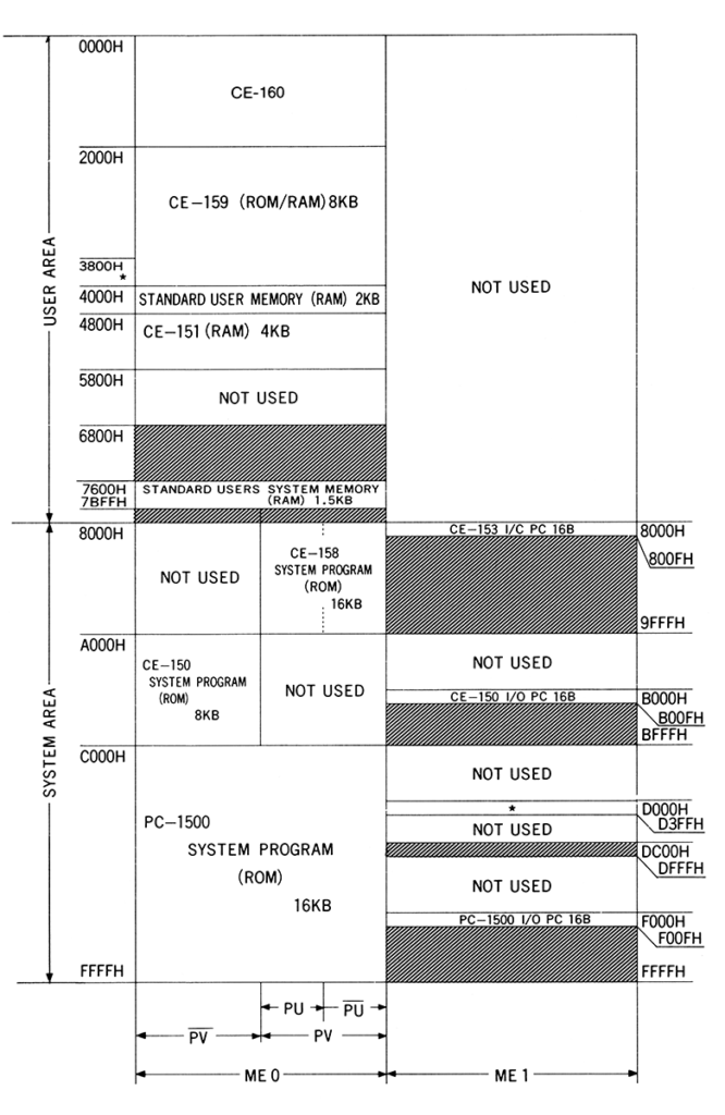
Chances are, the font bitmap data will be stored in the system program area of the ROM, which is 16KB total. This space starts at 0xC000 and ends at 0xFFFF. Chances are good that the font bitmap data will be in the same format I created for the PC-8 and the same with the Model 100.
It is possible to dump a portion of memory using the CSAVE command, record it to a WAV file, then use WAV2BIN (pocket tools), then search the file using a hex editor. However, I wrote a small program in BASIC instead, to search for the letter “A”:
REM SEARCH FOR THE 5 BYTE BIT PATTERN FOR THE LETTER "A" IN SYSTEM ROM

10 DATA 124,18,17,18,124,0
20 CLEAR : WAIT 0 : GOSUB 200
30 A = &C000
40 B = PEEK A : PRINT A;B;C
50 IF B <> C THEN GOTO 80
60 I = I + 1 : READ C : BEEP I
70 IF I = 5 THEN GOTO 100
75 GOTO 90
80 IF I <> 0 THEN GOSUB 200
90 A = A + 1 : IF A <= &FFFF THEN GOTO 40
100 END

REM RESET SEARCH

200 RESTORE
205 I = 0
210 READ C
220 RETURN
The program took a bit of time to run, but I wanted to find the pattern this way as opposed to using external tools, for the fun of it. Note that FOR / NEXT loops on the PC-2 cannot index beyond +/- 32,767, so I did not use that type of loop. I also added a BEEP for the indication of how many bytes in a row we have found. The PC-2 has a buzzer, why not use it?
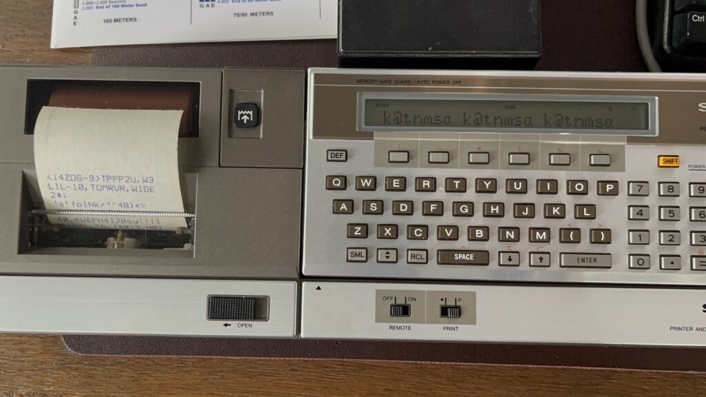
The result was a success! I found the character “A” beginning at address 0xFD45. Note that this was the case on my version of the PC-2. Now that I have found the letter “A” in ROM, I can use the font bitmap data included in ROM, rather than having to include my own within the program.
Connection to the Epson TM-T88V
The CE-158X is a direct compatible replacement for the Sharp CE-158. This means the software and port pinouts are identical. Even though more features are available on the CE-158X such as ROM variants, faster baud rates, and input support on the parallel port, the pinout of the parallel port is the same as the CE-158. When referring to the CE-158X I am also referring to the CE-158.
This means that two lines need to be swapped when connecting a standard Centronics parallel printer to the CE-158X:
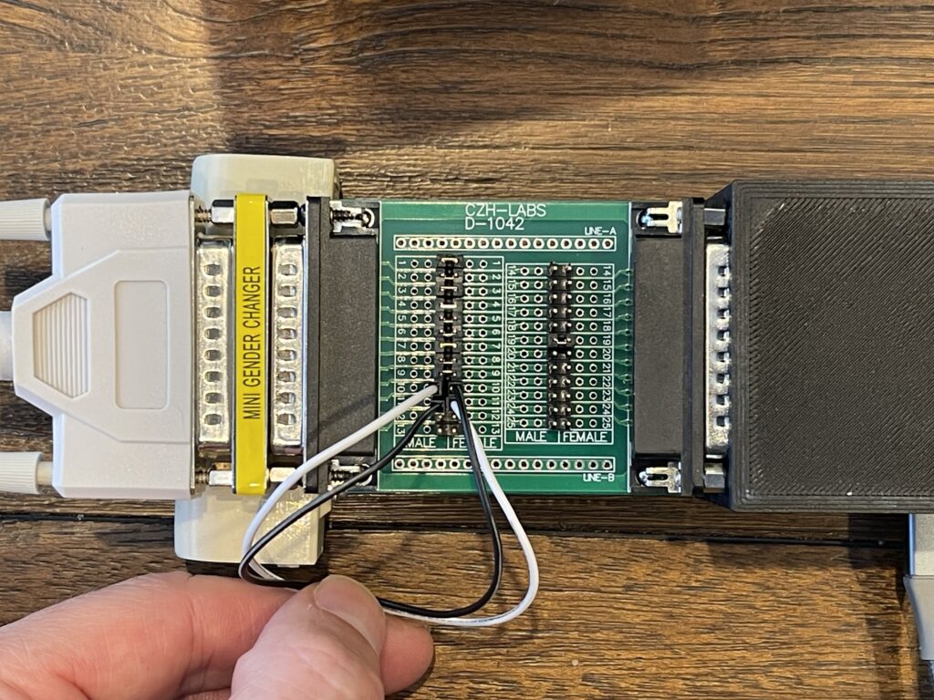
On the CE-158X, pin 10 is the input pin for “Busy”, while pin 11 is the output pin for “Init”. On a standard Centronics printer, these pins are reversed. Because there many be other pin incompatibilities, I used a breakout board with two 25-pin “D” style connectors. I placed this board in between the CE-158X and my printer cable connected to the Epson TM-T88V.
Pin 1 is the strobe output, pins 2-9 are the data pins, and 10 and 11 are busy and init. Many of the other pins are ground, according to the Centronics standard. However, because this is a CE-158X port and because it also supports input, I did not connect any of the other pins through except for one ground pin.
| Pin 12 – Used for input mode on CE-158X, L= Data is available (device can pull down if not needed). NC on standard CE-158. Pin 13 – NC on Sharp CE-158 Pin 16 – GND on both sides, but does not work if connected. Pin 17 – On CE-158X SLIN, Output, H=CE-158X LPT is in read mode, L= CE-158X LPT is in write mode. |
Therefore, I connected pins 1 through 9 through, swapped pins 10 and 11, and connected pin 19 through. The result worked! I saw print output on the Epson TM-T88V.
I redirected output to the parallel port using this command:
OPN"LPRT"Then I used the following to list a program to the printer:
LLIST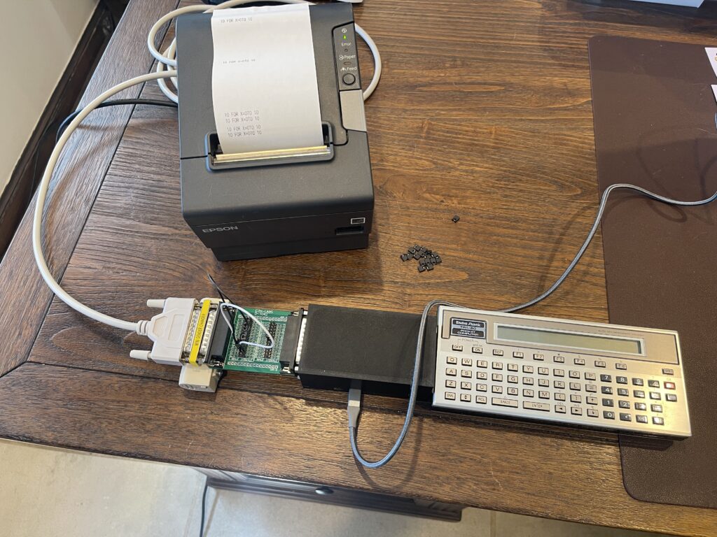
Now that I have the TM-T88V connected to the CE-158X and working with the standard LPRINT command in BASIC, I wrote an updated version of the banner program for the TP-10.
Since the font bitmap in the PC-2 is only 7 pixels high, each pixel on the bitmap is output as 6 characters on the TM-T88V. Further, to keep a somewhat 1:1 aspect ratio on the output to the printer, each row in the font bitmap is printed as 3 lines to the printer.
The program worked as expected, and thanks to the CE-158X, I can print to standard Centronics line printers.
The program source is below:
PC-2 BANNER FOR EPSON TM-T88V VERSION 1.2
LCD 5x7 FONT IN ROM STARTS AT 0xFD45

INIT AND LOOP THROUGH EACH CHAR IN STRING TO PRINT FOR BANNER

100 CLEAR : OPN"LPRT" : CONSOLE 0,0,1
110 X$ = CHR$(126) + CHR$(126) + CHR$(126) : X$ = X$ + X$
120 INPUT “Banner Text?”;T$
150 L = LEN(T$) : GOSUB 2500 : GOSUB 2000 : GOSUB 2100
160 FOR C = 1 TO L

READ TO LOCATION IN DATA ARRAY FOR CURRENT CHAR BITMAP

170 E$ = MID$(T$,C,1)
180 K = ASC(E$) : A = &FD45
190 A = A + ((K - 65) * 5)
200 B = PEEK(A)

READ EACH ROW IN BITMAP FOR THIS CHAR

210 FOR D = 1 TO 5
220 FOR R = 1 TO 3
230 G = 64
240 FOR F = 1 TO 7
250 H = B AND G : IF H > 0 THEN PRINT#-9, X$; : GOTO 260
255 PRINT#-9, "      ";
260 G = G / 2 : NEXT F
270 PRINT#-9, : NEXT R
280 A = A + 1 : B = PEEK(A) : NEXT D
290 GOSUB 2200 : PRINT#-9, : PRINT#-9, : GOSUB 2100 : NEXT C
300 GOSUB 2200 : PRINT#-9, : PRINT#-9, : PRINT#-9, : GOSUB 2300
310 GOSUB 2500 : END

REDEFINE "~" TO SOLID BLACK BOX, ENABLE CUSTOM FONT

2000 PRINT#-9, CHR$(27);"&";CHR$(3);CHR$(126);CHR$(126);CHR$(12);
2010 FOR M = 0 TO 35 : PRINT#-9, CHR$(255); : NEXT M
2020 PRINT#-9, CHR$(27);"%";CHR$(1);
2030 RETURN

SET LINE SPACING TO 0

2100 PRINT#-9, CHR$(27);"3";CHR$(0); : RETURN

SET LINE SPACING TO DEFAULT

2200 PRINT#-9, CHR$(27);"2"; : RETURN

CUT PAPER

2300 PRINT#-9, CHR$(29);"VB";CHR$(0); : RETURN

RESET PRINTER

2500 PRINT#-9, CHR$(27);CHR$(64) : RETURN
The ASCII source is linked below, in case you wish to send the program to the PC-2 via the CE-158X:
Use the commands below to send the banner program (ASCII format) using the CE-158X, and CoolTerm can be used. Be sure to set a transmit line delay of 500ms, with 0D as the delay character. This causes CoolTerm to pause 500ms after each carriage return (0x0D).
SETCOM 2400,8,N,1
SETDEV CI
CLOADa
Note: Do not send LF characters to the PC-2, only CR at the end of each line. If sending a file you have created or modified, use a program such as Notepad++ to remove all LF characters before sending to the PC-2. Also, be sure to include a line with a CR by itself at the end of the file. This signals the PC-2 that the transfer is complete.
Oddities with the Parallel Port
In my experimentation and trial and error, I had discovered that sending characters or byte values to the parallel port can be a bit tricky with the PC-2 and CE-158(X). What I found was, by default, the PC-2 will send a termination or FEED character after the 80th character sent to the printer.
This will of course interfere with printing in almost every example I can think of, for lines greater than 80 characters. This is especially true if printing graphics, bitmaps, or long escape sequences with text.
Of course there is a solution, but it is not well documented (in my opinion):
CONSOLE 0,0,1The first parameter sets the character count from the default of 80 to zero (before sending the FEED terminator. This effectively disables the automatic FEED terminator. The other two parameters are 0 or 1, which turn on CR and LF as the FEED terminator. This allows for one, the other, or both.
Earlier, I mentioned during my initial testing, I used the following to open the parellel port and print:
OPN"LPRT"
LPRINT "Hello Printer!"
There is an alternative, which does not require redirecting the LPRINT command to the parallel port:
PRINT#-9,"Hello Printer!"This might be more efficient, and to me, appeared to be functionally equivalent. However, I found that if OPN”LPRT” is not called before CONSOLE 0,0,1, then the CONSOLE statement had no effect, or, remained at defaults.
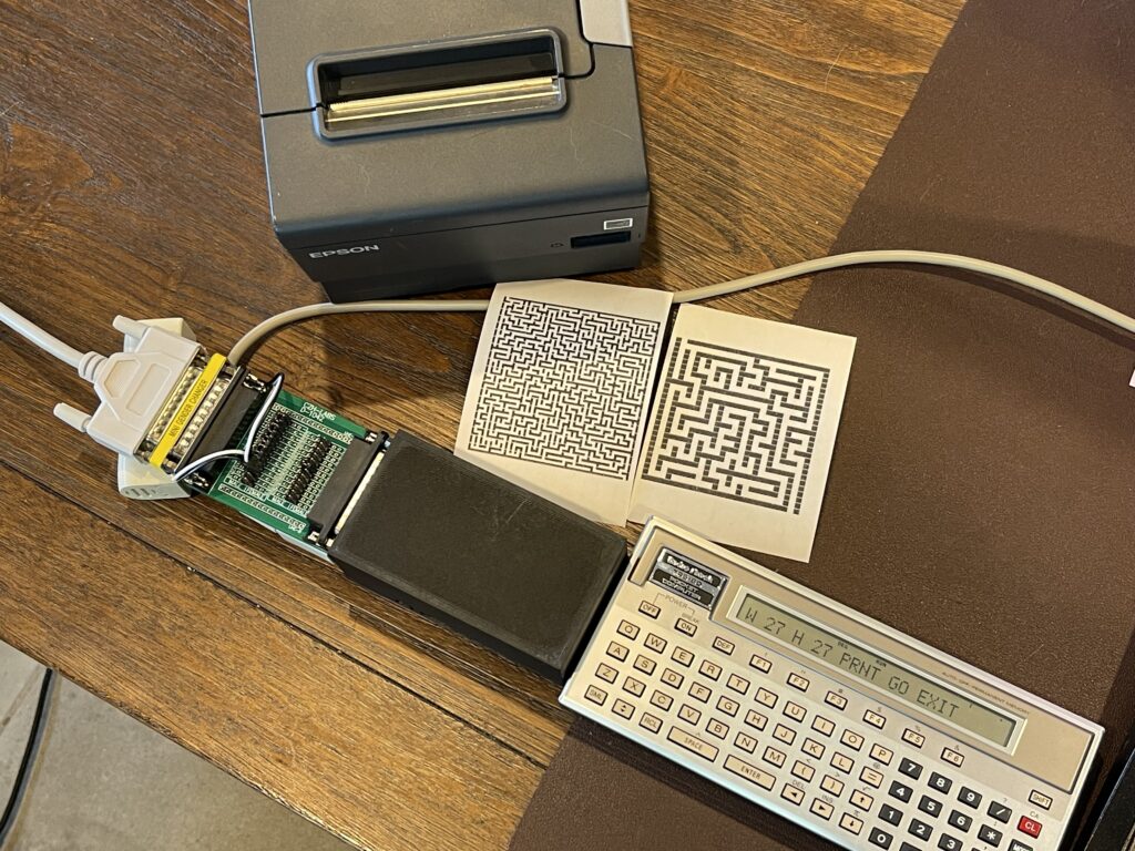
Maze Generator
I have recently begun writing maze programs for various pocket computers as another way to become familiar with various platforms. Since the CE-158(X) allows for many printer options, I can generate a maze and then print it. The challenge however, is to have enough memory (RAM) in order to generate the maze using the algorithm chosen. The simplest algorithm to use for maze generation is the backtracking algorithm. It can easily be programmed in BASIC.
The algorithm requires the canvas size to be odd in both width and height, for example, 19 x 19, and not 20 x 20. The requirement for the canvas dimensions being odd instead of even is due to the interior lines or blocks needed for the maze. For example, lets consider a maze on a canvas size of 27 x 3:

The maze itself has a single pathway, given the height of the canvas is 3 pixels, and the pathway is in between the top and bottom walls. The next incremental height we can consider would be 5 pixels high, not 4 pixels. The same can be said for the width, for example flipping the maze dimensions to a 3 x 27 canvas. Therefore, the height and width of the canvas must always be an odd number.
A maze generator would need an actual canvas to work with (either on the screen, in memory, or both), and it would need a stack to push and pop in order to track where the algorithm has “walked” before. The algorithm will “push” to the stack as it walks uncharted territory on the canvas, and “pop” from the stack when it needs to back up (if it hits a wall or adjacent open space). The backtracking algorithm randomly chooses a direction with each step, with one of four possible directions (up, down, left or right). It will not be able to choose a direction that would hit a wall or an adjacent open space. Therefore, if no directions are possible for travel in the current position, it must “backtrack” until a direction is possible.
Once the algorithm reaches back to it’s start position, the maze is complete. The start position is randomly chosen, and must be an odd number for the x and y coordinate. The odd numbered coordinates are spaces marked open during traversal of the path, and the even numbered coordinates become the walls of the maze. Therefore, each step in the “walk” is really 2 pixels away from the current position (skipping over the even numbered coordinates), in any direction. When a walk is performed and a position is marked as open, the adjoining position (the even coordinate) between the previous location and current location is also marked as open.
Below is an example of the backtracking algorithm animated with JavaScript from professor-l Elle:
There are some prerequisites which are needed for a computer to generate a maze using the backtracking algorithm:
- A dot addressable display and/or a printer
- Enough RAM to hold the canvas and/or stack for the desired width and height of the maze
- Random number generator
The PC-2 meets the prerequisites for a maze generator. Any line printer or thermal printer can be connected. Since I have an inexpensive Epson TM-T88V POS printer and the CE-158(X), I can connect it to the parallel port and print the mazes.
Since the PC-2 came with only 4KB of RAM built-in, a small maze would be possible to generate, but the 8KB expansion would be required to be able to generate a larger maze. This is especially true since the LCD display is not dot addressible, which means I will need to draw the canvas in memory, not on the display, which will consume much more memory.
Some computers with a dot addressable display have support to not only turning on or off a pixel at a time, but they also support reading the status of a pixel, eliminating the need to use additional user RAM for tracking pixel status. However, even though the PC-2 is dot addressable, it’s screen size, particularly the height, limits the vertical dimension to 8 pixels. Therefore, this version will not be drawn to the display, but will be printed only.
Memory Management
The larger the desired maze size, the more memory will be required to generate the maze. Since the PC-2 does not have a large enough dot addressable display, the maze needs to be generated in RAM and then printed.
The Epson TM-T88V can print 56 characters per line (for “Font B”). Due to the aspect ratio of this font, two horizontal characters are needed for each pixel for more of a square sized block when printing. This means that there are effectively only 28 “maze pixels” per line. Since the maze canvas size must be odd, this means the widest maze is 27 pixels. The height of course can extend as far as memory and paper length would allow for.
The memory requirement for a canvas size of 27 x 27 would be 729 bytes, which would fill the paper width of the TM-T88V as an example. In addition to the 729 bytes for the canvas, some more space would be needed for the stack.
Many pocket computers have PEEK and POKE commands in BASIC which allow for memory space to be consumed directly, byte by byte. Computers which do not have these commands are limited to the built-in variable management supported by the model. Luckily, the PC-2 supports PEEK and POKE for direct memory access.
This is advantageous because using numeric variables uses at least 8 bytes per variable on the PC-2. If I used a standard array on the PC-2 for the canvas or stack, this would increase memory usage by a factor of 8. This is because I need only 1 byte per value for the canvas and stack.
Unlike other computers, the PC-2 does not support multiple levels of variable sizes for numerics such as integer, single-precision, and double-precision.
In addition to needing memory for the canvas, I also need memory for the stack. The stack holds previously open spots when walking the canvas, using the backtracking algorithm. Since I need to track X and Y coordinates for the path, I need two positions in the stack for each coordinate. The total number of entries needed for the stack varies depending on the longest possible “path”.
The worst case scenario would be a path which starts in a corner and winds along the outside walls until reaching the center. This of course is nearly impossible given the randomness of the direction chosen. Therefore, the stack size is chosen as an average maximum. I chose a stack size of 1/2 the height and width of the canvas, and a single stack for the X coordinates and Y coordinates.
For a canvas size of 27 x 27, 1,458 bytes of memory would be needed for the canvas and stack, at most.
Safely Using POKE
The PC-2 has PEEK and POKE commands in basic which allows me to use a single byte of memory at a time, versus the 8 bytes per variable using the built-in variable or array management.
However, I cannot simply POKE values anywhere in memory on the PC-2, as the memory is managed by the PC-2 to provide storage space for variables and user programs, in addition to the system area.
Since I cannot hard-code the free memory location based on my PC-2 with or without a memory expansion installed, I need a way to dynamically calculate free memory amount and location at run-time.
Luckily the PC-2 provides a method to detect where free memory resides from within basic. This is done using the STATUS command, with a parameter of 2 and 3.
STATUS with a parameter of 2 returns the location in memory where the user program area ends.

STATUS with a parameter of 3 returns the location in memory where the user variable area ends.
In order to take advantage of the STATUS command, the PC-2 memory map is helpful:
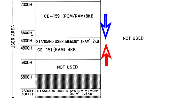
The key to making use of these two values from the STATUS command is understanding that the program space starts at the beginning of the user memory area and increases downward as programs are entered and space is used. I indicated this starting point and direction with the blue arrow in the picture above.
The user variable space starts at the end of the user memory area and the size increases in the upward direction (lower addresses) as variables are allocated. I indicated this starting point and direction with the red arrow in the picture above.
In theory, the free memory available for safe usage without interfering with variable space or overwriting program space would be in between these two values. At runtime, I can poll these two values and calculate the available free space.
This should be calculated at run time, as the maze program could be running along side other programs in memory, or, with a different amount of memory available. For example, it could be run on a PC-2 with no memory expansion installed, or with an 8KB (or more) expansion installed.
I ran a test of these values with an 8KB ram expansion installed and without. I also did this with and without a program loaded.
Without any memory expansion installed, the base 4KB of RAM:
STATUS 3: 18432 (&H4800) with no variables defined, 16817 (&H41B1) with a large array defined.

STATUS 2: 16582 (&H40C6) with no program entered, 16606 (&H40DE) with a small program loaded.
With an 8 KB RAM expansion installed:
STATUS 3: 24576 (&H6000) with no variables defined, 22961 (&H59B1) with a large array defined.

STATUS 2: 14534 (&H38C6) with no program entered, 15169 (&H3B37) with a program loaded.
Free memory can be verified with the MEM command. We can compare this value with my assumption that status 2 and 3 would indicate the same. I found that my testing was off a bit, by around 45 bytes.
Random Number Generation
The PC-2 supports random number generation using the RND function:
RND 10This will return a random number between 1 and 10, in decimal form. The smallest random number is 1, while the largest is specified by the parameter, and in this example, is 10.
The PC-2 will return the same sequence unless the keyword RANDOM is executed, which re-seeds the random number generator. Therefore, this keyword will be needed in my maze program.
Lack of Rounding Function
The PC-2 does not support a rounding function built-in. Since most random number generators return a decimal or double, I needed a function to convert this random number into an integer. Normally we simply multiply the random number generated by a number representing the desired upper limit. For example, in this case, I needed a random number from zero to three for indexing an array:
R = RND 4 - 1;In the example above, the random number “R” will be in the range between 0 and 3 as a double (or decimal). If you cast a double to an integer, you get just the whole number portion of the value. For example, 2.86 cast to an integer is 2. Of course, we likely want 3, and a rounding function would do this.
The simple solution to this would be:
R = INT(RND 4 + 0.5) - 1In the example above, integer “R” is assigned a value using a cast, but before the cast we add 0.5. This allows for the “rounding up” logic we expect from a rounding function.
No Modulus Function
The PC-2 has no modulus function, however, for the maze program, I use the modulus logic in previous versions of the maze generator to detect if a number is odd or even. This can be shortened to a bitwise operation such as X AND 1, and if the value is non-zero, then the value X is odd.
Maze Program Listing
After much trial and error, I was finally able to work through the various challenges with the PC-2 and printing. The effort was a success!
The program listing is below:
PC-2 MAZE GENERATOR VERSION 1.1

10 CLEAR : W = 27 : H = 27 : RANDOM : WAIT 0 : OPN"LPRT" : CONSOLE 0,0,1 : GOTO 9100
20 CLS : C = STATUS 2 + 1 : N = C + (W * H + 1) : S = N + (4 * 2) : SS = S
30 IF INT(SS+((W*H)/2)) >= STATUS 3 THEN PRINT "Not enough memory." : END

FILL WORKSPACE WITH CLOSED BLOCKS

50 FOR L = C TO C + W * H - 1 STEP 8 : POKE L, 0, 0, 0, 0, 0, 0, 0, 0 : NEXT L

CUT OPENING AT TOP

60 POKE C + 1, 1

RANDOM START SOMEWHERE

100 Y = INT(RND (H-2) + 0.5)
110 IF (Y AND 1) = 0 THEN 100
120 X = INT(RND (W-2) + 0.5)
130 IF (X AND 1) = 0 THEN 120
140 POKE C + Y * W + X, 1
150 POKE S, X, Y : S = S + 2
160 GOTO 220

POP NEXT OPEN SPACE OFF STACK

200 IF S = SS THEN 580
210 S = S - 2 : X = PEEK S : Y = PEEK (S + 1)

GET ADJACENT SPACES NOT OPEN YET

220 GOSUB 1000

IF NONE FOUND, POP PREVIOUS OPEN SPACE OFF STACK

500 IF D = 0 THEN 200

RANDOM CHOICE MADE, OPEN AND JOIN TO PREVIOUS

530 Z = INT(RND D + 0.5) - 1
540 L = PEEK (N + Z*2) : M = PEEK (N + Z*2 + 1) : POKE S, L, M : S = S + 2
550 POKE C + M * W + L, 1
560 POKE C + ((M+Y)/2) * W + ((L+X)/2), 1
570 X = L : Y = M : GOTO 220
580 POKE C + (H-1) * W + W-2, 1 : POKE C + (H-2) * W + W-2, 1
590 BEEP 1 : GOSUB 3500
600 GOTO 9100

FIND ADJACENT OPEN BLOCKS

1000 D = 0 : G = Y + 2 : I = Y - 2 : E = X + 2 : F = X - 2
1010 IF I > 0 AND PEEK (C + I * W + X) = 0 THEN POKE N + D*2, X, I : D = D + 1
1020 IF G <= H-1 AND PEEK (C + G * W + X) = 0 THEN POKE N + D*2, X, G : D = D + 1
1030 IF F > 0 AND PEEK (C + Y * W + F) = 0 THEN POKE N + D*2, F, Y : D = D + 1
1040 IF E <= W-1 AND PEEK (C + Y * W + E) = 0 THEN POKE N + D*2, E, Y : D = D + 1
1050 RETURN

REDEFINE "~" TO SOLID BLACK BOX, ENABLE CUSTOM FONT

2000 PRINT#-9, CHR$(27);"&";CHR$(3);CHR$(126);CHR$(126);CHR$(9);
2010 FOR M = 0 TO 26 : PRINT#-9, CHR$(255); : NEXT M
2020 PRINT#-9, CHR$(27);"%";CHR$(1); : RETURN

SET LINE SPACING TO 0

2100 PRINT#-9, CHR$(27);"3";CHR$(0); : RETURN

SET LINE SPACING TO DEFAULT

2200 PRINT#-9, CHR$(27);"2"; : RETURN

CUT PAPER

2300 PRINT#-9, CHR$(29);"VB";CHR$(0); : RETURN

SET FONT "B"

2400 PRINT#-9, CHR$(27);"M1"; : RETURN

RESET PRINTER

2500 PRINT#-9, CHR$(27);CHR$(64) : RETURN

PRINT MAZE USING CUSTOM CHAR

3000 GOSUB 2500 : GOSUB 2100 : GOSUB 2400 : GOSUB 2000 : T = C
3005 FOR Y = 0 TO H - 1
3010 FOR X = 0 TO W - 1
3020 U = PEEK(T) : IF U = 0 THEN PRINT#-9, CHR$(126);CHR$(126);
3030 IF U > 0 THEN PRINT#-9, "  ";
3040 T = T + 1 : NEXT X : PRINT#-9,
3050 NEXT Y : GOSUB 2500 : PRINT#-9, : PRINT#-9, : PRINT#-9, : GOSUB 2300 : RETURN

PRINT MAZE AT 180 DPI

3300 GOSUB 2500 : GOSUB 2100 : NH = INT(W * 8 / 256) : NL = ((W * 8) AND 255)
3310 FOR Y = 0 TO H - 1 : PRINT#-9, CHR$(27);"*";CHR$(33);CHR$(NL);CHR$(NH);
3320 FOR X = 0 TO W - 1
3330 L = 0 : IF PEEK (C + Y*W + X) = 0 THEN LET L = 255
3340 M = 0 : IF PEEK (C + (Y+1)*W + X) = 0 THEN LET M = 255
3350 N = 0 : IF PEEK (C + (Y+2)*W + X) = 0 THEN LET N = 255
3360 FOR G = 0 TO 7 : PRINT#-9, CHR$(L);CHR$(M);CHR$(N); : NEXT G
3370 NEXT X : PRINT#-9, CHR$(13);CHR$(10);
3380 Y = Y + 2 : NEXT Y
3390 GOSUB 2200 : PRINT#-9, : PRINT#-9, : PRINT#-9,
3400 GOSUB 2500 : GOSUB 2300 : RETURN

DETERMINE PRINT DENSITY

3500 IF W <= 27 THEN GOSUB 3000 : RETURN
3510 GOSUB 3300 : RETURN

VALIDATION

4000 IF W > 63 THEN W = 63
4010 IF W < 3 THEN W = 3
4020 IF H > 239 THEN H = 239
4030 IF H < 3 THEN H = 3
4040 W = W - (W AND 1) + 1
4050 H = H - (H AND 1) + 1
4060 RETURN

MENU

9000 CLS : USING "###" : PRINT "W";W;" H";H;" PRNT GO EXIT"; : USING
9010 RETURN
9100 BEEP 1 : GOSUB 9000
9110 K = ASC INKEY$
9120 IF K = 20 THEN 20
9130 IF K = 17 THEN CLS : INPUT "Width:";W : GOSUB 4000 : GOSUB 9000
9140 IF K = 18 THEN CLS : INPUT "Height:";H : GOSUB 4000 : GOSUB 9000
9150 IF K = 21 THEN END
9160 IF K = 19 THEN GOSUB 3500
9170 GOTO 9110
If you wish to load the maze program via the serial port, the file below has the source:
This version of the maze generator includes a menu for the selection of the width and height, validation, and a memory check to ensure enough free memory is available for the chosen canvas size.
For a 27 x 27 canvas, the generation took approximately 3 minutes and another minute to print.
Since the TM-T88V includes a graphics mode with 180 dpi resolution, I can switch to that mode and print a maze with a canvas as wide as 63. For a 63 x 63 canvas, it took approximately 20 minutes to generate and 17 minutes to print.
It should be noted that the base 4 KB of RAM is not enough to run this maze generator – the program itself needs more than 4 KB to load via the serial port on the CE-158(X). The maze generator, at least the initial version (1.0) requires 1,928 bytes of program space.
Even though the Radio Shack RS-232 module did not have a parallel port, there are several Epson POS printers which have a serial interface. One of those models could be connected to the RS-232 port and the program could be modified to output to the serial port instead of the parallel port.
If this were the early 80’s, I could pitch my maze generator to Tandy and help them sell their RS-232 module.
Commercial Software
You can still find quite a bit of the commercial software on archive.org, including relevant books for the PC-2:
https://archive.org/search?query=PC-2+Pocket+computer
Final Thoughts
Restoring the plotter and RS-232 modules and seeing them still working after 40 years was amazing. I always wanted one of these back in the late 80s and now I was able to play around with one.
Even though there isn’t really a purpose or use for one of these computers today, having one fully working and seeing how they worked is a reminder of how far things have come in terms of technology.
The PC-2 is also a great platform to learn microprocessors and design of software, ROM, RAM, and external bus interfaces.
Even though the cassette interface can be used to load and save programs to cassette tapes, it’s easier to use a PC and utilities that convert ASCII files to and from WAV files for the PC-2 / PC-1500.
I plan to experiment with some assembly level programming on this platform. I have some ideas for useful apps, and I have extensive experience with machine level coding (assembly) in embedded systems. I’ll post related articles as I make progress with a few ideas for apps.