

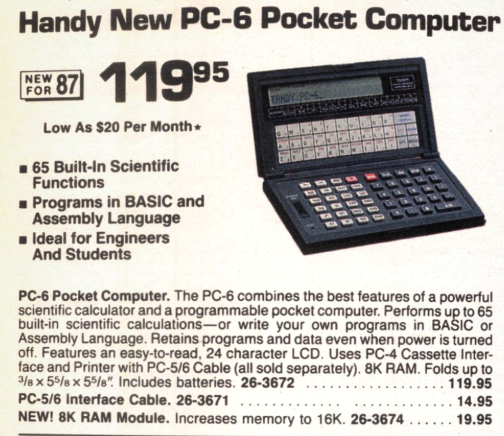
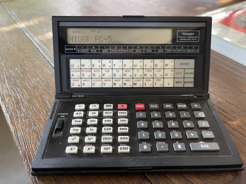
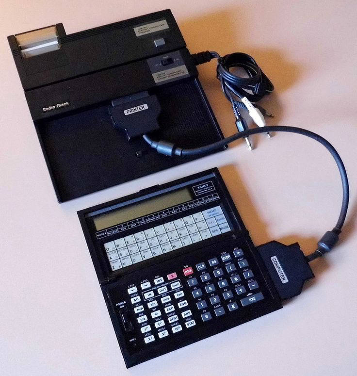
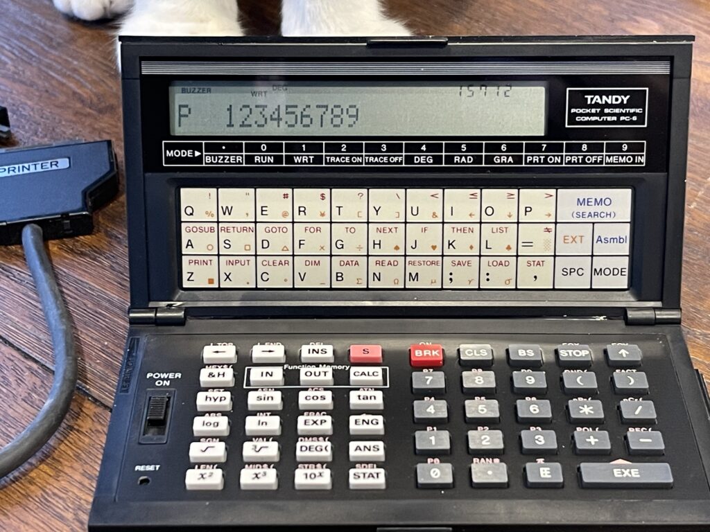
Tandy PC-6 Pocket Computer
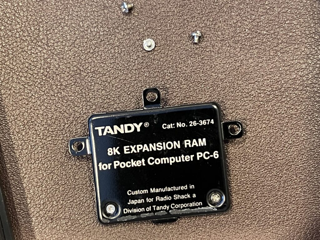
The PC-6 was the best (in my opinion) rebadged Casio pocket computer Radio Shack sold. It had the most memory out of the box, supported an additional 8KB memory expansion module, peripherals such as a printer and cassette interface, and “assembly” language simulation.
The PC-6 was the third Casio model Radio Shack released, the prior two were the PC-5 and PC-4. Radio Shack continued with their switchover to Casio models with the PC-6.
The program space with the Casio models was segmented into 10 areas. These areas are P0 through P9. This differs from the Sharp models where the program space was not segmented at all. If you wanted to store more than one program, you had to do so by getting creative with the line numbers (keeping programs segmented). With the Casio models, the segmented program areas allow for up to 10 programs, each in their own space.
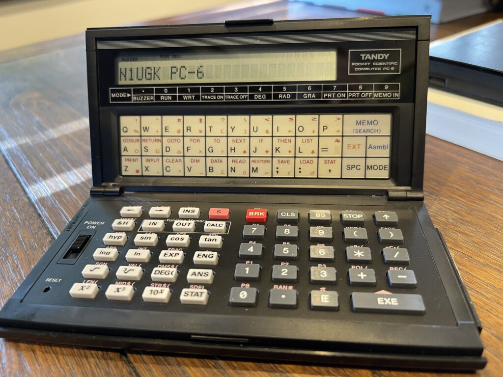
This model had a 24 character LCD display, an expansion port, and a two tone buzzer. It ran off two CR-2032 batteries and used a CR-1220 as a memory backup. This was very handy for keeping your programs intact when changing the main batteries.
Radio Shack Pocket Computer Releases
The first pocket computer, the PC-1 was introduced for catalog year 1981 and the last catalog year for a pocket computer was 1992 with the PC-6.
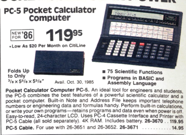
The PC-5 was its predecessor, which was sold for only one catalog year. It was basically the same model as the PC-6, except that it had 4KB of RAM and no possibility for adding a memory expansion module. The PC-5 did not have the reset button exposed – the reset button was under the back cover. There are a few differences between the PC-5 and PC-6, the biggest BASIC difference is the PC-5 does not support the DIM statement, only the DEFM statement. Of course this changes some of the variable handling a bit if trying to run a PC-6 program on a PC-5.
The PC-5 model is a rare find on auction sites. Perhaps because this model was sold for just one year before being replaced by the PC-6. Or, perhaps not as many of them were sold. Another model which was sold for only one year was the PC-8, and I have seen far more PC-8’s for sale than the PC-5’s.
The PC-6 was released in catalog year 1987 and sold through catalog year 1992. It is the longest running pocket computer model Radio Shack offered. This model is still very easy to find on auction sites such as eBay because they were sold for so many years more than any other model Radio Shack offered.
I prefer the Sharp models of pocket computers rebadged by Radio Shack because their peripherals were better designed and I preferred their form factor. For example, the PC-2 in my opinion was the best and most capable rebadged pocket computer Radio Shack ever sold. There really was not an equivalent rebadged Casio model.
However, the PC-6 was the best of the rebadged Casio line.

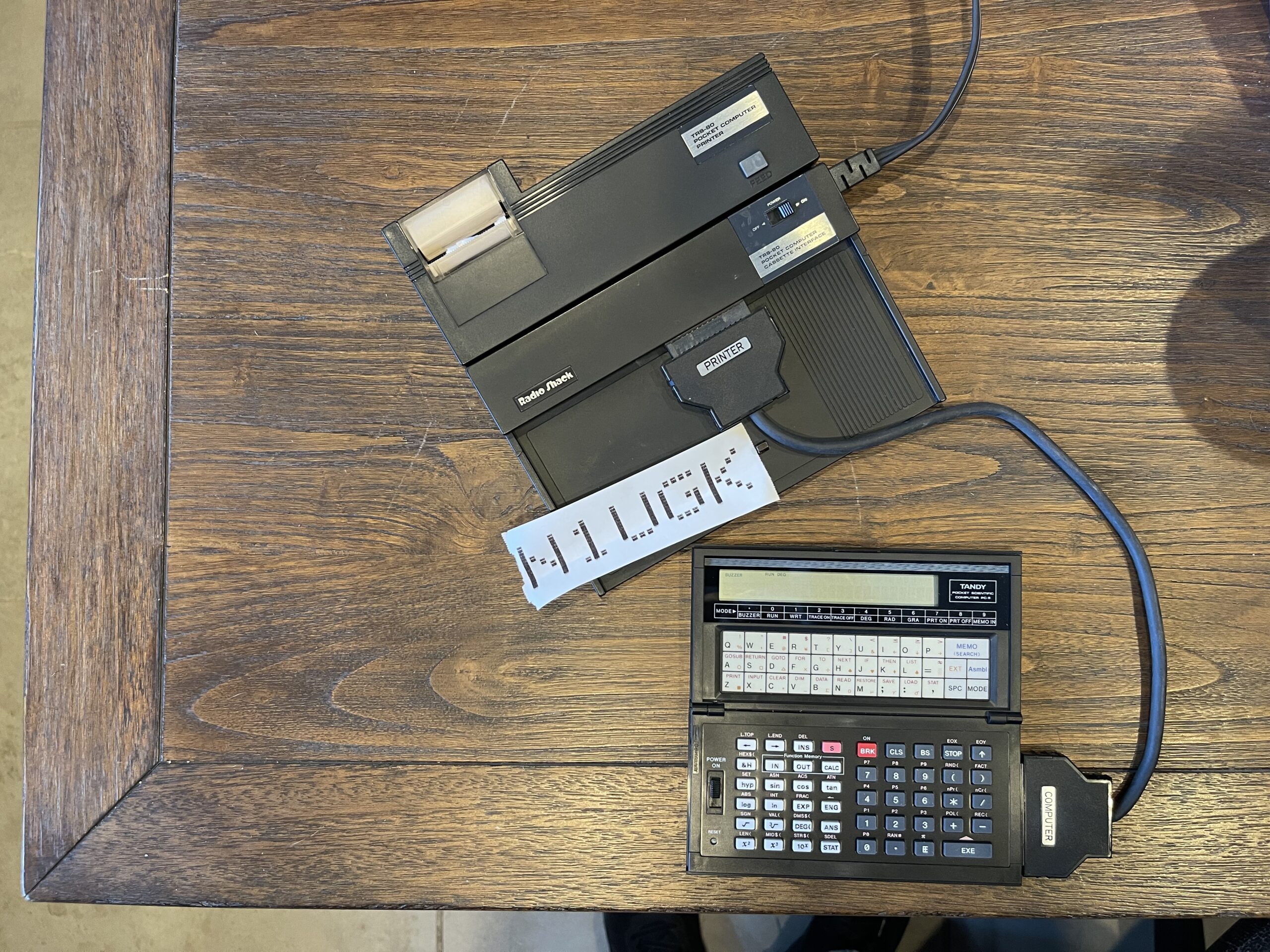
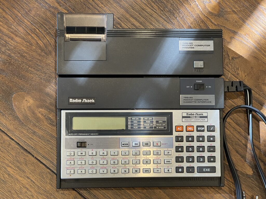
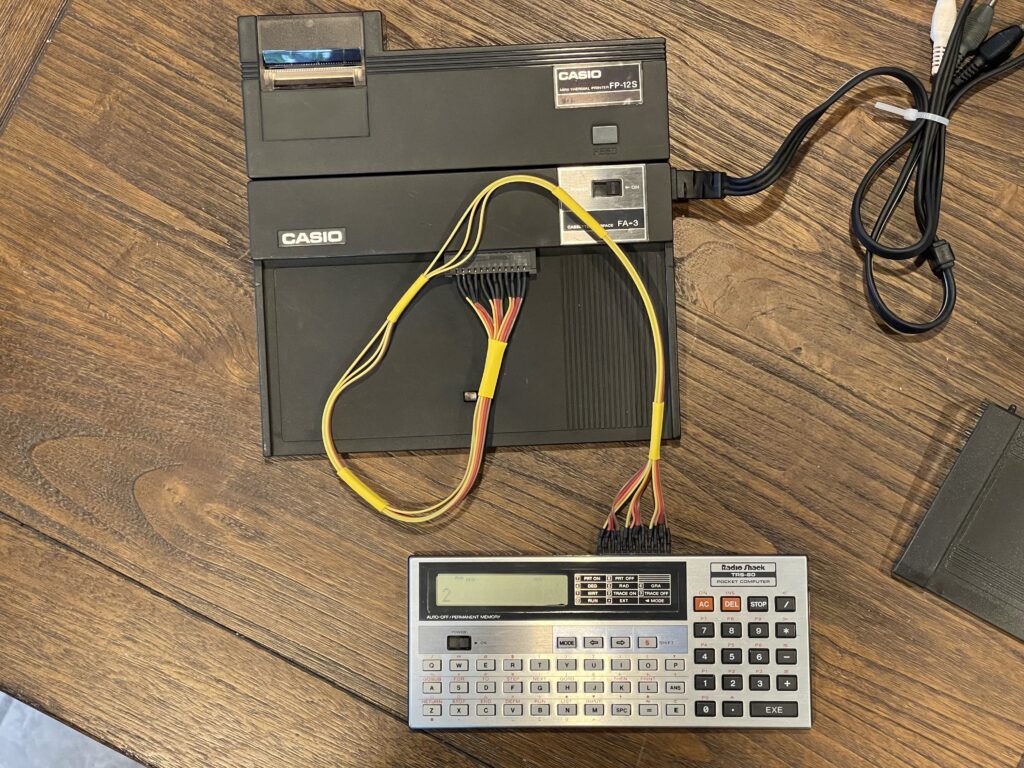
The Radio Shack PC-5 and PC-6 pocket computers were Casio FX-780P and FX-790P models respectively. The printer and cassette modules for these models were separate units, unlike the rebadged Sharp pocket computers Radio Shack sold which had one-piece printer cassette modules. Similar to the PC-8 where it used the PC-3 printer and cassette module, the PC-5 and PC-6 used the PC-4 printer and cassette modules. There was a specific cassette module for these Casio models, the FA-5 which plugged directly into the side of the pocket computer. These are not easily found these days.
Over the years there have been a few PC-5’s pop up on eBay. I found one recently that was new in the box and the sales receipt was in between the pages in the user guide. The PC-5 was purchased at a Radio Shack in Brooklyn NY on November 26, 1985 for $119.95.

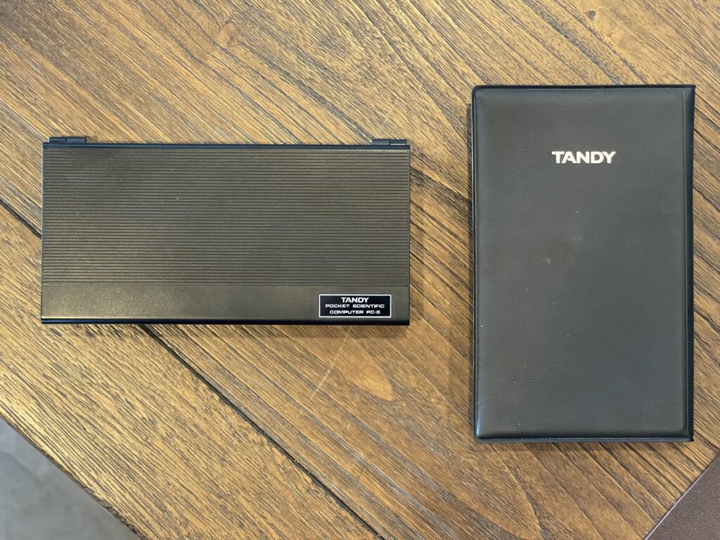
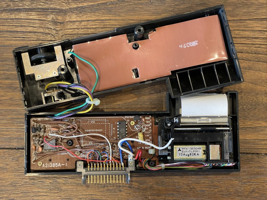
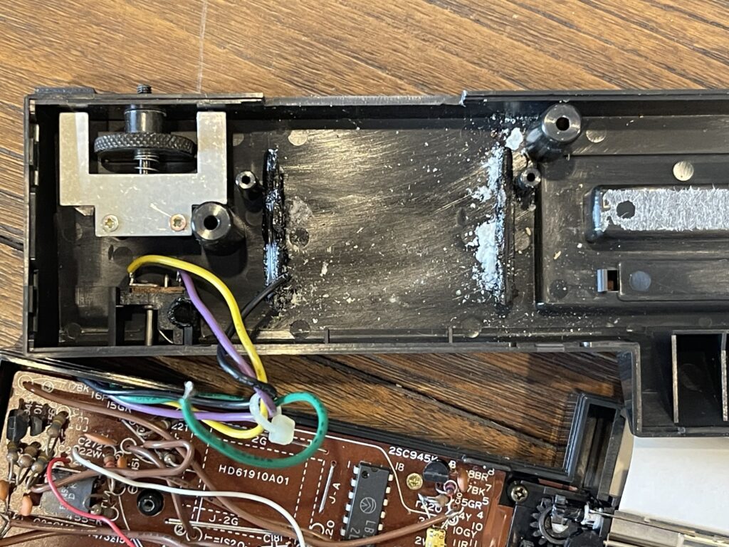
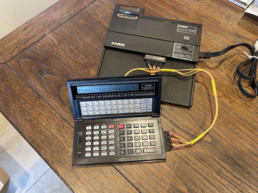
“Clamshell” Design
The PC-6 (and its predecessor, the PC-5) were “clamshell” designs, which provided for a small form factor for the pocket, with decent button sizes. However, this exposed the PC-6 to some unfortunate possibilities for a shortened lifespan.
The plastic clasp that holds the PC-6 shut is known to snap. The ribbon cable which connects the two halves together adds a concern of possible wear over time. I have not heard of this happening frequently. Lastly, the hinges are known to break, and when that happens, the ribbon cable would then be subject to additional stress.
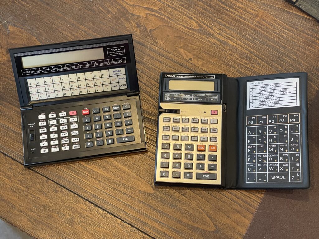
This reminds me of the unfortunate design of the PC-7, another rebadged Casio model Radio Shack sold. I owned one of these and that folding cover eventually wears down and makes button presses a challenge as they age.
Because I owned the PC-7 when it came out, when I hold a PC-6, I immediately appreciate the hard plastic and metal case. If you were to actually put a PC-6 in your pocket, it would survive. It is more durable than the PC-7 in your pocket.
My PC-5 had a dim LCD display which seemed to improve on occasion. I found that the sliding power switch was the culprit and a simple cleaning with IPA solved that issue.
As mentioned earlier, the PC-5 and PC-6 had a 24-character LCD display, which is fairly wide. They supported upper and lower case characters as well as some basic notation symbols and card suit symbols for example.

Peripheral Connection Challenge
Because the PC-5 and PC-6 pocket computers were “clamshell” designs, they could not simply dock to a printer or cassette module. A special cable was required, and this cable is very difficult to find. Before jumping into how they connect, let’s take a look back at the PC-4:

The PC-4 had a separate printer and cassette interface. In the picture above, the two piece printer and cassette module was quite a hack. If you were to connect just the printer to the PC-4, for example, you would need to attach the plastic spacer/holder to the PC-4, then plug the printer onto the back of the spacer, using a thumbscrew to hold it together. On the other hand, if you had the cassette module, you can stack the PC-4, cassette interface, then printer together, again, with a thumbscrew holding it all together.
When assembled together, if you have to change the two “AA” batteries in the cassette module, you would need to take the printer off the back of it so that you can remove the battery cover. Further, to charge the printer, the Casio user guide states that it must not be connected to either the cassette module or the computer.
Finding and Fixing a PC-4 Printer
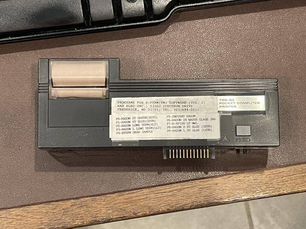
The PC-4 printer, Radio Shack catalog number 26-3652 (also Casio FP-12S) is thermal, using 1 1/2″ wide paper. This is quite small, compared to the PC-1, PC-2, and PC-3 printers (Sharp variants), which used 2 1/4″ paper. Similar to the 2 1/4” paper, this thermal paper is easily found on Amazon and it is inexpensive.
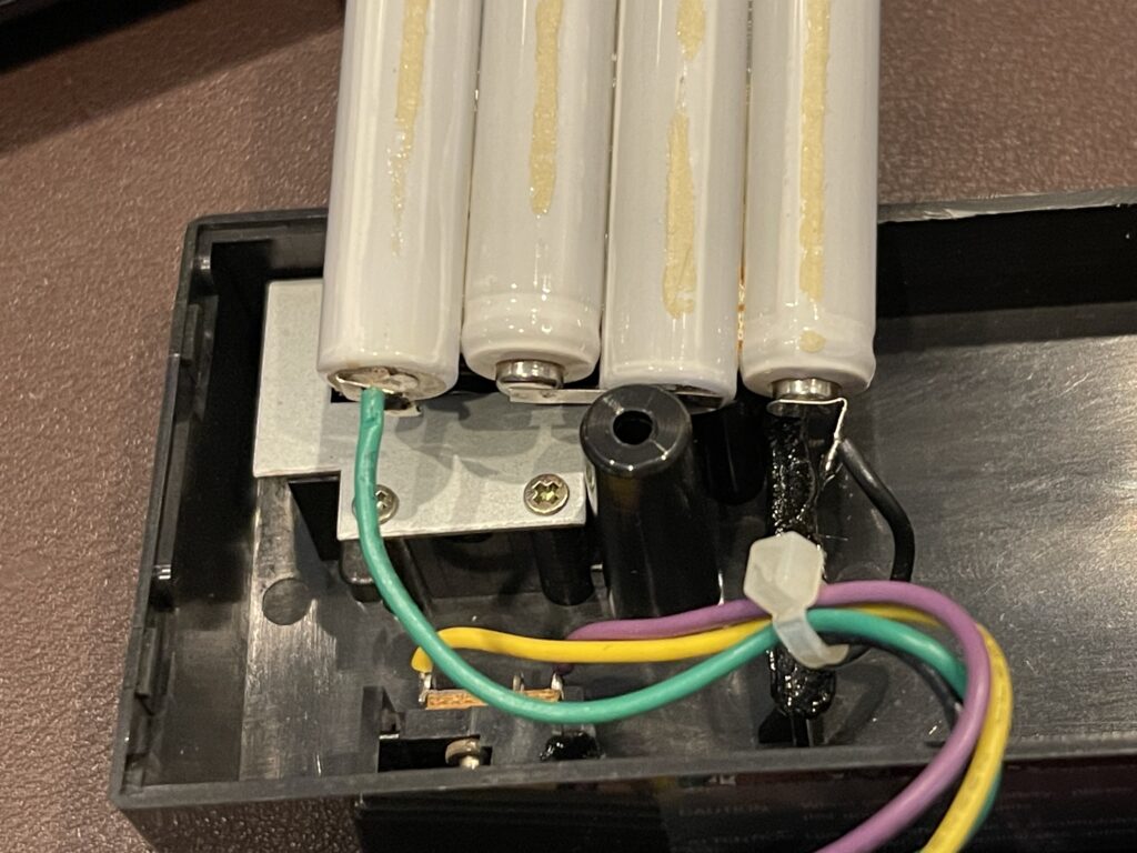
I found one of these printers on eBay with the box. As with all of the other various pocket computer printers such as the printers for the PC-1, PC-2 and PC-3 for example, the NiCd battery pack needed to be replaced. Luckily there was very little leakage.

The Radio Shack version has a noise shield over the battery pack, which prevented any of the leakage or dust from getting into the PCB. The Casio FP-12S has no such shield. The wiring to the battery needs to be carefully noted. In the case of the Radio Shack model, the green wire is negative and the black wire is positive with the connection to the battery pack.
The Casio printer is really quite cheaply made compared to the Sharp models. For example, the battery pack was held in place by melted plastic on either side of the battery. To replace the battery, I ended up using a hot glue gun to hold the replacement in place. The replacement I used was a ready-made AAA NiMH 800mAh pack.

The printer had a similar mechanism to the PC-3 printer where the print head moves on a worm gear which also feeds the paper as it returns back to the left after printing a line.
After replacing the battery pack, I charged up the battery and connected my PC-4. The printer worked! It was a bit odd seeing such a small printout, compared to other models. It appears the printer I acquired was made on or after 1982, by the stamp on the motor. My Casio FP-12S was made in 1988.
I remembered that the user guide for the printer mentions that neither the pocket computer nor the cassette interface can be connected to the printer when it is being charged. The charger for this model is 9 volts DC, center pin negative, with 20mA output.
I have since picked up some spare units, printer cables and printers. It is very interesting to see examples of how these products were used back then. I have often seen labels on the pocket computers and printers which give a hint of their usage in the field.
The owner’s manual for the Casio FP-12S (same as the Radio Shack PC-4 printer, 26-3652) is included below:
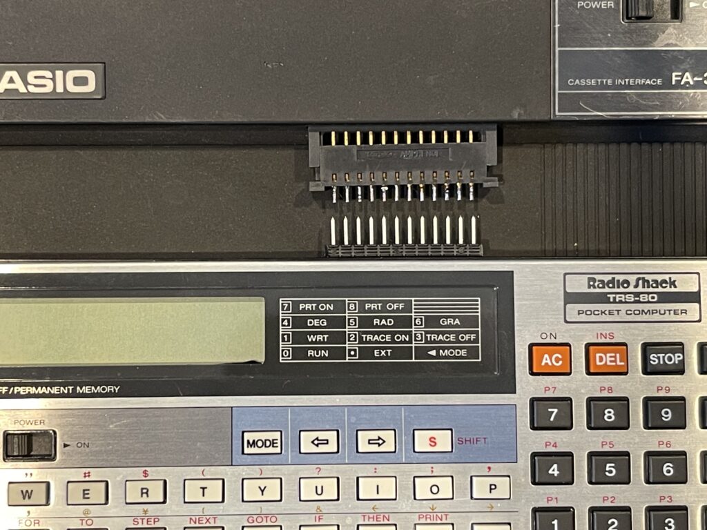
The PC-6 Peripheral Port
The PC-6 unfortunately cannot simply plug directly into the printer and/or cassette interface. Technically it is possible to turn the PC-6 sideways and connect it, but that is likely to put stress on the connector and lead to premature wear.
Radio Shack (and Casio) sold a cable which connected between the PC-6 and the printer or cassette interface. This cable is extremely difficult to find today. The Casio part number is the SB-2, the Radio Shack catalog number is 26-3671.
The peripheral interface is a 12-pin connector which is proprietary. It has a keyed direction to it, meaning the official connection cable would plug in only one way on each side.
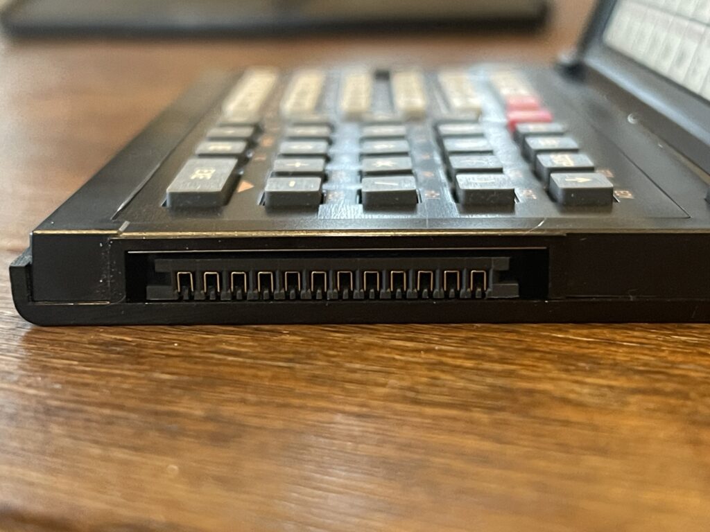
This is the same connector that was on the PC-5 (similar model) and the PC-4.
A Printer not Commonly Found
I suspect most owners of the PC-6 did not bother with the small printer offered for this pocket computer, which is likely why the printer and the cable are rarely seen any longer. As a reminder, the printer that was offered for the PC-6 (and the PC-5) was the PC-4 printer.
The PC-4 (first version) was extremely limited in both memory and BASIC support. The PC-4 was a rebadged Casio PB-100. For example, it had only 544 bytes available for programs. Without BASIC support for printing (it can only echo the screen to the printer) it really was one of the worst of the pocket computer models. Perhaps this is also why the PC-4 printer is not commonly available any longer.
Perhaps the PC-4 was useful for basic functions and limited programs, but you could do little else with it. Without support for DATA statements (until the second version), bit wise functions, limited string functions, only 544 bytes for programs, and limited printer support, the banner program is a challenge on this model.
The PC-4 did support a 1KB RAM expansion module, but those are as common today as the SB-2 cable is today. A second version of the PC-4 was released, which added a few BASIC commands, such as DATA, READ, and RESTORE.
New Use for the PC-4 Printer
Since the PC-6 is far more capable than the PC-4, attaching it to my PC-4 printer would offer more capability for use of the printer. Even though the support in BASIC for printing is the same as the PC-4, and there are no bitwise operators, the PC-6 has far more memory to work with. It supports DATA statements and other additional BASIC commands which allow for more interesting programs to be written. Perhaps even the banner program can be written for the PC-6.
However, unable to find the SB-2 cable meant I could not simply plug in the PC-6 to the printer to experiment with it.
Building a Cable
I chose to build a cable myself; it was only 12 pins.
The connector on the PC-4, PC-5, and PC-6 is unique. It was not something I was able to find online at an electronic parts supplier, yet.
I took the female connector from an old PB-100 (PC-4):
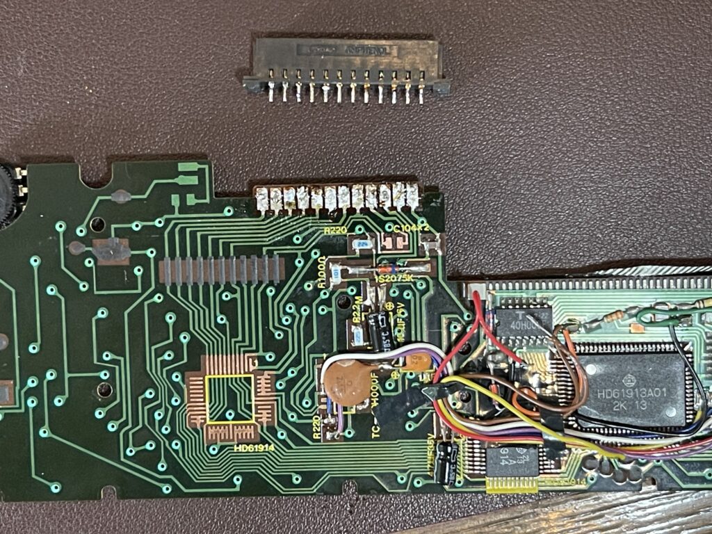
This was a bit easier than trying to find a compatible equivalent on an electronics part supplier site. Having these spare units around for “parts” calculators and modules is sometimes handy.
I was especially careful not to use too much heat removing the connector from the PCB. I used some solder wick and pried up each pin carefully one by one until the connector was free from the PCB.
For the male end of the cable, it turns out that standard header blocks fit well. I happened to have a few of those available for testing the fit.
I did not have ribbon cable wide enough on hand, so I ended up using three pieces of four-wire ribbon cable and some heat shrink to keep it together.
To help avoid shorts and to add a little durability to the connectors, I added small heat shrink to each soldered pin connection.
The cable is quite fragile and care must be taken to avoid damaging it when unplugging either end. Perhaps I will find a way to surround the connections with plastic or similar methods for adding some strength to each side of the connection.
Testing the Cable
Because I value the PC-6 more than the PC-4, I used the PC-4 as my test before plugging in the PC-6. In reality, I did actually probe the cable with a continuity tester to ensure no shorts and was careful to get the orientation correct.
The cable worked! I turned the print mode on and saw my calculations printed on the printer.
Without any problems connecting the PC-4, I connected the PC-6, and the same test worked perfectly. I also tested saving to tape and loading from tape.
Update
Since publishing the first revision of this article, I found the 26-3671 interface cable on eBay. It was completely by chance – I had a saved search alert me to new listings for a PC-6. I received an alert and reviewed the pictures for a new listing for a PC-6 when I saw one of the photos showed the cable, Radio Shack catalog number 26-3671. It was also mentioned as included in the listing description. The price for the PC-6 was reasonable, and had the usual broken hinges, but all I needed was the cable.


The PC-6 was delivered, with the cable, and upon testing it, it worked!

The seller of the PC-6 with the cable did not include or mention the cassette interface nor printer, which is interesting since they had possession of the interface cable. Before the item arrived, I was curious if the PC-6 also had the 8KB memory expansion installed, since the original owner had purchased the interface cable. When the PC-6 arrived, I took off the back cover and sure enough, as an added bonus, the 8KB memory expansion was there:
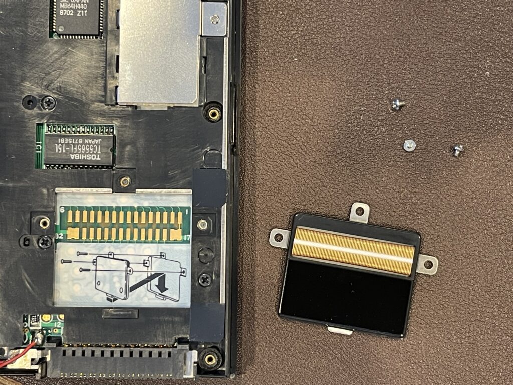
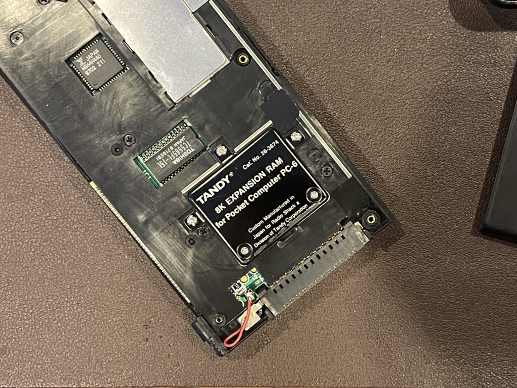
Since the PC-6 I found had broken hinges, I took the memory expansion module out and installed it in the PC-6 I already had.
PC-6 BASIC Support
I have been using my banner program as a baseline for capability and comparison across multiple vintage portable computer models. Each model has specific advantages or disadvantages, usually around its printer type (thermal versus pens or ink), BASIC support, and how much memory it takes to accomplish the task.
Similar to the PC-4, the PC-6 does not offer specific printer support in BASIC other than echo to the printer via the PRINT statement. This is done by using the MODE 7 command to turn the printer echo on, the PRINT command(s) would then echo to the printer, and the MODE 8 command turns the printer echo off.
The PC-6 supports far more BASIC commands than the PC-4 (at least the first version). However, it supports similar limited character and string functions. It does support the DATA command with READ and RESTORE.
The PC-6 is missing some convenient BASIC features which are useful for the banner program. It does not have a command to convert a character to an ASCII integer. This is necessary to break down the string to print into individual characters and then convert each character into indexes to the bitmap font data. It also does not support a bitwise AND function.
In order to write a banner program for this Pocket Computer model, I will need to work around these limitations. Of course, the objective is to use as little memory as possible, without obscuring the code too much.
Challenges for the Banner Program
Since the PC-6 does not offer a way to read the internal ROM address space like I could with the PC-2, I will need to use my font bitmap data via DATA statements versus reading the bitmap from ROM.
I will need to work around the limited character functions available on the PC-6. I will need to find a new way to index the font bitmap data for each character to print for the banner.
The PC-6 does not support bitwise AND logic, which means I will need to find a new way to inspect the font bitmap data and translate it for each line to print.
This printer can print 20 characters per line. The font width is 7 characters (rotated and one character per pixel when printing), and the printer width unfortunately is one character short for a perfect match for a 1:3 scale upwards. This means a scale of 1:2 is the most we can do for printing each character. This leaves 3 character spaces on the top and bottom of the banner.
Only one string variable exists, “$” which allows for more than 7 characters in length. DIM statements do not provide extension of this size limitation. The MID$ function can operate only on this special string variable.
Advantages of this Printer
Unlike the PC-8 (and PC-3) printer, it is possible to print a string without an automatic line feed on this printer. This means that I would not need a string variable 20 characters in length in order to print a full row of characters on this printer. I am able to issue multiple print commands without an automatic line feed occurring (unlike with the PC-3 printer).
PRINT "XX";Another advantage of this printer is it supports a few special characters, mainly a “block” character which is useful for the purpose of printing a banner.
PRINT "▓▓";Banner Program Adapted
Due to the lack of an available command to convert a character to an integer (such as an ASCII code), I was not able to index the font bitmap data using the ASCII code to derive an offset into the data array.
Instead, I simply added an indexer character before each 5 byte bitmap sequence. I then indexed the array by searching for the letter currently needed. This method consumed 39 more bytes than previous iterations of the banner program where DATA sections were necessary (A-Z, 0-9, a space, and 2 quotes).
Luckily, the PC-6 has a function which converts a string in hex to a numeric value, &H:
170 READ A$
180 A$ = "&H" + A$
190 B = VAL(A$)
This allows me to store the bitmap data as a hex string for each byte in the bitmap data. This limits the use of memory to just two bytes per row in the font bitmap. The PC-8 for example, without the hex to numeric function, requires storage of some values using 3 digits (any value greater than 100). For example, the PC-8 would require this statement for the letter A:
1 DATA 124,18,17,18,124Two of these bytes require 3 characters. The PC-6 equivalent can be:
1 DATA 7C,12,11,12,7COver the span of the entire bitmap data, this saved approximately 20 bytes. This offset some of the additional memory needed to create the index to find the characters.
Without a bitwise AND command, I modified the logic to look at the lowest bit in the current value for the bitmap row. If the value was odd, then the lowest bit is a 1. On the other hand, if the value was even, then the bit was a zero. The PC-6 has a FRAC command which can be used to determine whether division has a remainder. I used division by 2 as the argument to this function to determine even or odd.
320 FOR F = 1 TO 7
330 H = FRAC(B/2) : IF H = 0 THEN 350
340 PRINT "▓▓"; : GOTO 360
350 PRINT "  ";
360 B = INT(B/2) : NEXT F
I used the INT command to round off the division by 2 to right shift the remaining bits in the font bitmap row.
However, this approach prints starting from bit 0, as opposed to starting at bit 7 as with all previous iterations of the banner program. Therefore, I switched the logic around to print starting with the last letter in the banner and worked backwards. I also had to flip the font bitmap data accordingly.
Testing the Banner Program
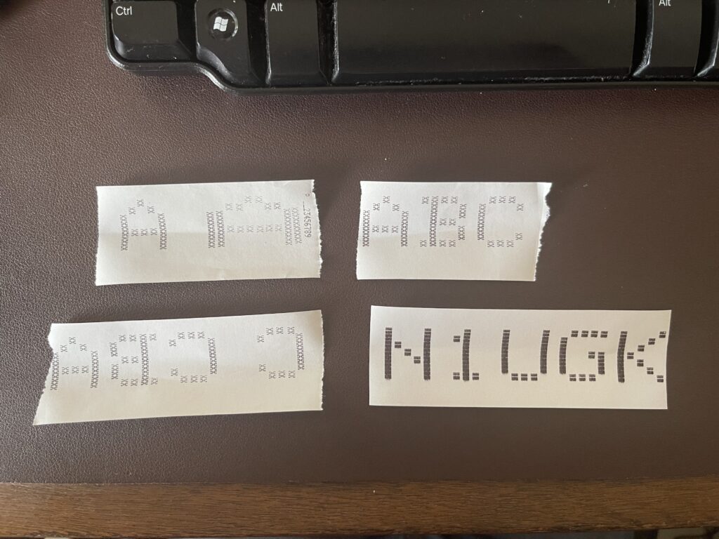
I thought at first I was not going to be able to create a version of the banner program for the PC-6, but in the end, I was able to do so. Not only that, this version is quite efficient (minus the font bitmap data), using only 909 bytes of memory.
There were several attempts at the program, with modifications on each iteration which slowly arrived at the final output:
I included the PC-6 banner program as a WAV file, if you have a PC-6 or PC-5 and the cassette interface:
I included the banner program listing below. Be sure to ignore the highlighted comment statements, I added these to illustrate the various sections of the program flow. If you wish to add more characters to the data array, remove the last zero byte, add the characters in the same format, and then append a zero byte.
TANDY PC-6 BANNER PROGRAM VERSION 1.1

1 DATA A,7C,12,11,12,7C,B,36,49,49,7F,41
2 DATA C,22,41,41,41,3E,D,3E,41,41,7F,41
3 DATA E,41,49,49,49,7F,F,1,9,9,9,7F
4 DATA G,39,49,41,41,3E,H,7F,8,8,8,7F
5 DATA I,0,41,7F,41,0,J,1,7F,41,40,20
6 DATA K,41,22,14,8,7F,L,40,40,40,40,7F
7 DATA M,7F,2,C,2,7F,N,7F,10,8,4,7F
8 DATA O,3E,41,41,41,3E,P,6,9,9,9,7F
9 DATA Q,5E,21,51,41,3E,R,46,29,19,9,7F
10 DATA S,32,49,49,49,26,T,1,1,7F,1,1
11 DATA U,3F,40,40,40,3F,V,7,18,60,18,7
12 DATA W,7F,20,18,20,7F,X,63,14,8,14,63
13 DATA Y,3,4,78,4,3,Z,43,45,49,51,61
14 DATA 0,3E,45,49,51,3E,1,0,40,7F,42,0
15 DATA 2,46,49,51,61,42,3,31,4B,4D,49,41
16 DATA 4,10,7F,12,14,18,5,39,45,45,45,27
17 DATA 6,30,49,49,4A,3C,7,3,5,79,1,1
18 DATA 8,36,49,49,49,36,9,1E,29,49,49,6
19 DATA " ",0,0,0,0,0,0
100 CLEAR
110 INPUT “TEXT”;$
120 MODE 7 : L = LEN($)
130 FOR C = L TO 1 STEP -1

READ TO LOCATION IN DATA ARRAY FOR CURRENT CHAR BITMAP

140 E$ = MID$(C,1) : RESTORE : READ A$
150 IF A$ = E$ THEN 170
160 READ U$,V$,W$,X$,Y$,A$ : GOTO 150
170 READ A$

READ EACH ROW IN BITMAP FOR THIS CHARACTER

200 FOR D = 1 TO 5
205 A$ = “&H” + A$ : PRINT "  ";
215 B = VAL(A$)
220 FOR F = 1 TO 7
230 H = FRAC(B/2) : IF H = 0 THEN 250
240 PRINT "▓▓"; : GOTO 260
250 PRINT "  ";
260 B = INT(B/2) : NEXT F
270 PRINT ""

NEXT CHARACTER

280 READ A$ : NEXT D
290 PRINT ""
300 NEXT C

DONE

310 PRINT "" : MODE 8
320 END
Maze Program
Another program that is interesting to write for these pocket computers is a maze program. Since the PC-6 has a printer option, I can generate a maze and then print it. The challenge however, is to have enough memory (RAM) in order to generate the maze using the algorithm chosen. The simplest algorithm to use for maze generation is the backtracking algorithm. It can easily be programmed in BASIC.
The algorithm requires the canvas size to be odd in both width and height, for example, 19 x 19, and not 20 x 20. The requirement for the canvas dimensions being odd instead of even is due to the interior lines or blocks needed for the maze. For example, lets consider a maze on a canvas size of 27 x 3:

The maze itself has a single pathway, given the height of the canvas is 3 pixels, and the pathway is in between the top and bottom walls. The next incremental height we can consider would be 5 pixels high, not 4 pixels. The same can be said for the width, for example flipping the maze dimensions to a 3 x 27 canvas. Therefore, the height and width of the canvas must always be an odd number.
A maze generator would need an actual canvas to work with (either on the screen, in memory, or both), and it would need a stack to push and pop in order to track where the algorithm has “walked” before. The algorithm will “push” to the stack as it walks uncharted territory on the canvas, and “pop” from the stack when it needs to back up (if it hits a wall or adjacent open space). The backtracking algorithm randomly chooses a direction with each step, with one of four possible directions (up, down, left or right). It will not be able to choose a direction that would hit a wall or an adjacent open space. Therefore, if no directions are possible for travel in the current position, it must “backtrack” until a direction is possible.
Once the algorithm reaches back to it’s start position, the maze is complete. The start position is randomly chosen, and must be an odd number for the x and y coordinate. The odd numbered coordinates are spaces marked open during traversal of the path, and the even numbered coordinates become the walls of the maze. Therefore, each step in the “walk” is really 2 pixels away from the current position (skipping over the even numbered coordinates), in any direction. When a walk is performed and a position is marked as open, the adjoining position (the even coordinate) between the previous location and current location is also marked as open.
Below is an example of the backtracking algorithm animated with JavaScript from professor-l Elle:
There are some prerequisites which are needed for a pocket computer to generate a maze using the backtracking algorithm:
- A dot addressable display and/or a printer
- Enough RAM to hold the canvas and/or stack for the desired width and height of the maze
- Random number generator
The PC-6 meets the prerequisites for a maze generator. The printer is required, and the base 8 KB of RAM is all that is needed (for up to a 19 x 19 maze). The 8 KB memory expansion would be useful for a taller canvas size, if needed.
This model does not have a dot addressable display which means I will need to draw the maze using a canvas in user memory. This will require a bit more user RAM than other pocket computer models would require.
Memory Management
The larger the desired maze size, the more memory will be required to generate the maze. Since the PC-6 does not have a dot addressable display, the only output for the generated maze would be the printer. The PC-4 printer has a maximum character width of 20 characters. Since the dimensions of the maze must be odd-numbered, this limits the maximum maze width to 19. Of course, the height can exceed 19 if desired.
Many pocket computers have PEEK and POKE commands in BASIC which allow for memory space to be consumed directly, byte by byte. Pocket computers which do not have these commands are limited to the built-in variable management supported by the model.
For example, the worst case scenario would be a pocket computer which does not support PEEK and POKE and uses 8 bytes for each numeric variable. This is the most common memory management scheme for simple pocket computers. If I needed to generate a maze on a 19 x 19 canvas in memory, this would consume 2,888 bytes for the canvas alone, not to mention the stack needed for the backtracking algorithm. If PEEK and POKE were supported, then only a single byte would be needed for each pixel on the canvas and stack value. This would be the best case scenario.
Unfortunately the PC-6 does not support PEEK and POKE, nor does it support “half-precision” variables, meaning numeric variables will consume 8 bytes each. Luckily this model supports the DIM function, whereas the PC-5 does not. For example, to allocate a 25 position array, the format would be:
DIM C(24)The array of 25 variables would consume 200 bytes of user RAM. Therefore, for a canvas size of 19 x 19, 2,888 bytes of user RAM would be required.
In addition to the canvas, I need memory for the stack. The stack holds previously open spots when walking the canvas, using the backtracking algorithm. Since I need to track X and Y coordinates for the path, I need two positions in the stack for each coordinate. The total number of entries needed for the stack varies depending on the longest possible “path”. The worst case scenario would be a path which starts in a corner and winds along the outside walls until reaching the center. This of course is nearly impossible given the randomness of the direction chosen. Therefore, the stack size is chosen as an average maximum. I chose a stack size of 1/2 the height and width of the canvas, and one stack for the X coordinates, and another stack for the Y coordinates.
For a 19 x 19 canvas size, the stack would require another 2,888 bytes total.
Results
The maze program works and it is not as slow as I would have thought, for a canvas size up to 19 x 19. Due to the printer character dimensions being more tall than wide, a 1:1 aspect ratio is accomplished by printing two blocks horizontally for every pixel on the canvas. This aspect ratio is shown in the sample printout below, on the left. The result of printing one character per pixel is shown to the right. The latter results in a somewhat “stretched” appearance.

The line spacing is not controllable on these simple printers.
A WAV file for the maze program is included below:
The program listing for the PC-6 version of the maze program is included below:
TANDY PC-6 MAZE GENERATOR VERSION 1.0

10 CLEAR : W = 19 : H = 19 : DIM C(W,H) : DIM N(3,1)
20 DIM A(W*H*0.5) : DIM B(W*H*0.5)
30 W = W - (W-(INT(W / 2)*2)) + 1
40 H = H - (H-(INT(H / 2)*2)) + 1

CUT OPENING AT TOP

80 C(1,0) = 1

RANDOM START SOMEWHERE

100 Y = RND(RAN# * (H-2),-1) + 1
110 IF FRAC(Y/2) = 0 THEN 100
120 X = RND(RAN# * (W-2),-1) + 1
130 IF FRAC(X/2) = 0 THEN 120
140 C(X,Y) = 1
150 A(S) = X : B(S) = Y : S = S + 1
160 GOTO 210

POP NEXT OPEN SPACE OFF STACK

200 IF S = 0 THEN 580
205 PRINT "[]"; : S = S - 1 : X = A(S) : Y = B(S)

GET ADJACENT SPACES NOT OPEN YET

210 GOSUB 1000

IF NONE FOUND, POP PREVIOUS OPEN SPACE OFF STACK

500 IF D = 0 THEN 200

RANDOM CHOICE MADE, OPEN AND JOIN TO PREVIOUS

530 Z = RND(RAN#*(D-1),-1) : PRINT "][";
540 L = N(Z,0) : M = N(Z,1) : A(S) = L : B(S) = M : S = S + 1
550 C(L,M) = 1
560 C((L+X)/2,(M+Y)/2) = 1
570 X = L : Y = M : GOTO 210

CUT OPENING AT BOTTOM, BEEP AND PAUSE, THEN PRINT

580 C(W-2,H-1) = 1 : C(W-2,H-2) = 1
590 BEEP
610 GOSUB 3000
620 END

FIND ADJACENT CLOSED BLOCKS

1000 D = 0 : G = Y + 2 : I = Y - 2 : E = X + 2 : F = X - 2
1010 IF I <= 0 THEN 1030
1015 IF C(X,I) = 1 THEN 1030
1020 N(D,0) = X : N(D,1) = I : D = D + 1
1030 IF G >= H - 1 THEN 1050
1035 IF C(X,G) = 1 THEN 1050
1040 N(D,0) = X : N(D,1) = G : D = D + 1
1050 IF F <= 0 THEN 1070
1055 IF C(F,Y) = 1 THEN 1070
1060 N(D,0) = F : N(D,1) = Y : D = D + 1
1070 IF E >= W - 1 THEN 1090
1075 IF C(E,Y) = 1 THEN 1090
1080 N(D,0) = E : N(D,1) = Y : D = D + 1
1090 RETURN

PRINT CANVAS

3000 MODE 7
3005 FOR Y = 0 TO H - 1
3010 FOR X = 0 TO W - 1
3020 IF C(X,Y) = 0 THEN PRINT "▓"; : GOTO 3040
3030 PRINT " ";
3040 NEXT X
3050 PRINT ""
3060 NEXT Y
3070 PRINT "" : PRINT "" : PRINT ""
3080 MODE 8 : RETURN
Variables
A - Open Space Stack, X
B - Open Space Stack, Y
C - Canvas
N - Adjacent closed spaces
Z - Index chosen within closed spaces
D - Closed space count
E - Current X position + 2
F - Current X position - 2
G - Current Y position + 2
I - Current Y position - 2
H - Canvas height
L - Temp
M - Temp
S - Open Space stack size
W - Canvas width
X - Current X position
Y - Current Y positionTo change the aspect ratio to be closer to 1:1, set the width not to exceed 9 and change the following lines:
3020 IF C(X,Y) = 0 THEN PRINT "▓▓"; : GOTO 3040
3030 PRINT "  ";
Utilities
Marcus von Cube has posted a series of CASsette IO Utilities which can be used to convert WAV files to ASCII output and vice versa. This is very helpful to avoid typing entire programs into the PC-5 / PC-6 and to be able to visualize an entire program at once on a PC screen.
The list730 and bas730 executables were what I found to be compatible and work with not only the PC-5 and PC-6, but the PC-4 as well. List730 converts a WAV file to an ASCII file. I used Audacity to “amplify” WAV files I have recorded from the cassette interface and then ran them into list730. Bas730 can be used to convert an ASCII file to a WAV file to be loaded into the pocket computer.
Passwords
The PC-5 and PC-6 support a “password” feature which if set, prevents listing or modification of programs in the pocket computer. When saving the programs to tape, the password is stored with the program(s). When loading the program(s), the password is loaded as well. This prevents attempts to bypass the password by copying of a program to tape, loading and reading the contents.
The password can be sniffed out using the list730 executable with a recording from the PC-5 or PC-6. As a test, I wrote a one-line program in P0 then I set the password on my PC-5 to “TEST”. I then used the SAVE ALL command to save the programs to tape. I recorded the output using Audacity, then fed the WAV file into list730:
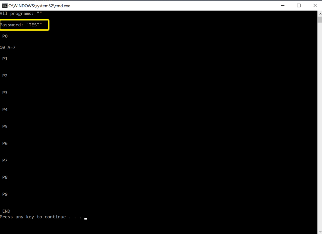
The password “TEST” is clearly visible in the output. Using the method above, one could recover the password on any PC-5 or PC-6 using the cassette interface, Audacity, and CASsette IO Utilities.
Pocket Computer Universal Interface
The Pocket Computer Universal Interface (PCUI) works with the PC-5 and PC-6, as well as similar Casio models with the same 12-pin interface port. The PCUI can be used as a printer cassette interface for these models since the printer cassette is not easy to find these days.
The PCUI has both CMOS and TTL level interface capabilities, and luckily the PC-6’s expansion port is TTL level.


The PCUI can save programs and variable contents from the PC-6 to its micro SD card and load programs from the micro SD card back to the PC-6 using SAVE and LOAD as with the cassette interface. The 12-pin connector is at TTL level, and the interface uses a shared bus. The cassette I/O is done via handshaking and bits on one of the four data lines on the bus.
In addition to emulating the cassette interface, the PCUI also emulates the printer interface, allowing you to use a standard line printer such as a dot matrix or any other parallel or serial interface printer.
The printer interface was quite a challenge to get working, as the printer for these models grabs hold of the bus and pulls nibbles out of the pocket computer’s memory at a specific location. The pocket computer places nibbles into this memory location when printing.
A demonstration of the PCUI with these models is included below:
Because the Casio bus protocol on these devices do not force a carriage return after 20 characters (the width of their respective printers), when using the PCUI, you can output a line as wide as your attached printer from BASIC for example.
Further, because many printers support defining custom characters, the PCUI will define the Casio specific non-ASCII characters in an ESC/POS printer for example so that the Casio-specific special characters will print those characters as the original printers would.
Final Thoughts
I am glad I built an interface cable to be able to connect the PC-6 to the printer and cassette modules. I had been waiting for an SB-2 cable to pop up for sale for quite awhile. Even though I eventually found a cable, it was fairly simple to build one. Without a printer or cassette interface, this pocket computer just is not as useful to me as one that has this option.
I went in to this project with a heavy bias toward the Sharp pocket computers, mainly on my experience with the PC-7 (read my intro for the PC-8) and the PC-4. The PC-7 had no peripheral support and the PC-4 had such anemic BASIC support (first version) and limited memory out of the box, it was the most challenging to write a banner program for.
Getting my hands on a PC-6, which like the Model 100, I would see year after year in the Radio Shack catalogs, was a great experience. Not only was it far more capable than the PC-4 and PC-7, it has a good feel when using it. The buzzer option for keypresses provides positive feedback that the key was recognized. This was especially helpful for the membrane part of the keyboard. The feel and responsiveness was better than the membrane keyboard on the PC-7.
Note that the buzzer in this model is simply either a low or high tone. It does not support variable pitch nor duration.
The PC-6 has so many more features than I have described here. For example, it has more scientific and math related functions, a data bank, and an assembly simulator.
One should not get too excited about the assembly feature in this computer. It is just a “simulator”, intended for teaching and learning assembly in general. It does not support reading/writing outside of the simulator environment, printers, nor other I/O. This is nothing like the assembly support on the PC-2 for example. A good write up of the history of why this feature exists in both the PC-6 and the PC-5 is here.
After going through the exercise to adapt the banner program to this model, it forced me to become more familiar with the Casio flavor of BASIC and its advantages and disadvantages. As it turned out, I came out with a more optimized version of the banner program than on the PC-8.
Overall, this experience has definitely changed my mind on Casio pocket computers, at least this model. My frame of reference for pocket computers is what Radio Shack rebadged and sold. They did not always pick the best that Casio nor Sharp had available. The PC-2 was quite a hit, and a good choice. Throughout the years, Radio Shack seemed to focus mainly on price and portability as a priority when choosing the models to rebadge and sell.
I have also created a simple matching game for the PC-6.
The service manual for the PC-6 is below: