
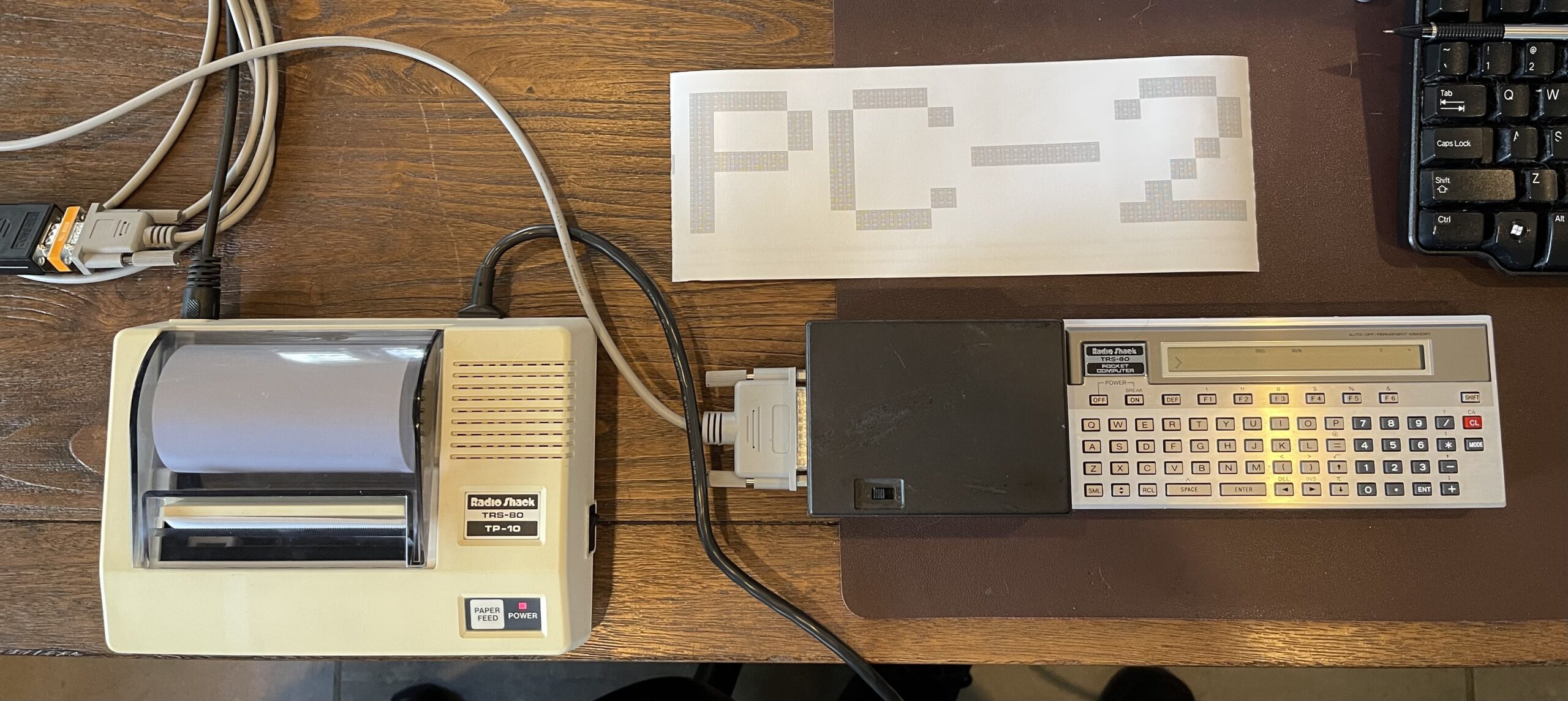
Connecting the TP-10 Printer to the PC-2
After acquiring a TP-10 thermal printer and connecting it to the Model 100, I figured I could do the same with my TRS-80 PC-2. Throughout this post, I refer to the PC-2, which is a rebadged Sharp PC-1500. These pocket computers had a printer/cassette module which was actually a miniature 4-color plotter with a cassette interface. I had fixed up the one I had, and the one major drawback to these models is the pens are hard to find and expensive. The advantage to the thermal printers is that you can still find paper for them today, or, you can cut paper to fit. Further, there is no ink, pens, or cartridges to find or maintain.
Printing without the “Pens”
Connecting the TP-10 to the PC-2 would allow for a nice way to print (although not in color) without consuming the pen ink in the original plotter. As a sample program to test this idea, I chose to write a PC-2 version of my banner program. However, a few requirements need to be met before such a version is attempted. First, I need a way to connect a serial printer to the PC-2.
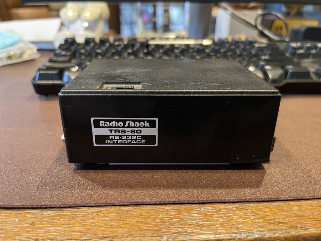
Before going any further, I should point out that a difficult-to-find piece of hardware is necessary to connect a serial printer to the PC-2. Radio Shack released an RS-232 adapter for the PC-2 (catalog number 26-3612) and Sharp released an RS-232 and parallel port combo (CE-158) adapter for the PC-1500. If you have either one of these, you’re able to connect a serial printer (2400 baud or below) to the PC-2. Luckily I had picked one of these up years ago. I posted about this unit previously.
This interface will support a baud rate of 600, no parity, 1 start bit and 2 stop bits. This is the interface requirement for the TP-10. Now that this requirement is met, I can move to the next challenge.
Banner Program Variants
My original version of the banner program was made for the PC-8, which used just over 900 bytes of RAM. In that version, I had to include the font bitmap data, as the undocumented PEEK command does not work with the ROM address space, only the 2KB RAM area.
The second version of the banner program I wrote was for the Model 100. In that version, I referenced the font bitmap data within the ROM of the Model 100. This version gave me all of the printable characters without any extra program space or effort to create the characters in a font bitmap.
Finding the Characters in ROM
In order to use the same method for the banner program for the PC-2 (as I did with the Model 100), I would need to know where and how the font bitmap data is stored within the system ROM. Similar to the Model 100 version, I searched the world wide web for a PC-1500 ROM dump with a mapping of the areas of the ROM. I did not want to spend too much time searching, and I did not find what I wanted.
I looked through the PC-1500 Technical Reference Manual, and spotted a memory map:
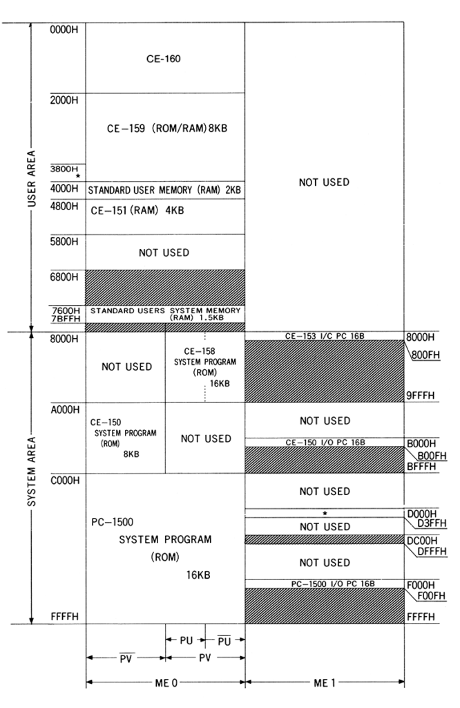
Chances are, the font bitmap data will be stored in the system program area of the ROM, which is 16KB total. This space starts at 0xC000 and ends at 0xFFFF. Chances are good that the font bitmap data will be in the same format I created for the PC-8 and the same with the Model 100.
It is possible to dump a portion of memory using the CSAVE command, record it to a WAV file, then use WAV2BIN (pocket tools), then search the file using a hex editor. However, I wrote a small program in BASIC instead, to search for the letter “A”:
SEARCH FOR THE 5 BYTE BIT PATTERN FOR THE LETTER "A" IN SYSTEM ROM

10 DATA 124,18,17,18,124,0
20 CLEAR : WAIT 0 : GOSUB 200
30 A = &C000
40 B = PEEK A : PRINT A;B;C
50 IF B <> C THEN GOTO 80
60 I = I + 1 : READ C : BEEP I
70 IF I = 5 THEN GOTO 100
75 GOTO 90
80 IF I <> 0 THEN GOSUB 200
90 A = A + 1 : IF A <= &FFFF THEN GOTO 40
100 END

REM RESET SEARCH

200 RESTORE
205 I = 0
210 READ C
220 RETURN
The program took a bit of time to run, but I wanted to find the pattern this way as opposed to using external tools, for the fun of it. Note that FOR / NEXT loops on the PC-2 cannot index beyond +/- 32,767, so I did not use that type of loop. I also added a BEEP for the indication of how many bytes in a row we have found. The PC-2 has a buzzer, why not use it?
The result was a success! I found the character “A” beginning at address 0xFD45. Note that this was the case on my version of the PC-2. Now that the second challenge is done, the next will be the hardware flow control for the TP-10.
Hardware Flow Control
As with the Model 100 and the TP-10 experiment, I will need to monitor the status line from the TP-10 before sending a byte to it. Otherwise the printout will be affected by buffer overrun.
In order to read the CTS line on the RS-232 module, I can use the INSTAT command. To test my connection, I connected the TP-10 to the PC-2 RS-232 module, and typed INSTAT. The PC-2 returned “3” with the TP-10 on. With the TP-10 off, INSTAT returned a “7”. Unlike the Model 100, with the PC-2 the CTS line is not inverted. Noting the difference between the two values received from INSTAT, the 3rd bit in is the CTS bit.
Communication Parameters
Since the TP-10 needs a connection at 600 baud, no parity, 8 bits, 1 start and 2 stop bits, I used the SETCOM command with a value of 600,8,N,2:
SETCOM 600,8,N,2The RS-232 module for the PC-2 has a built in terminal program. I connected the PC-2 to the TP-10, typed a few characters, and it did not work as I expected. The printer was printing a graphics block no matter what I typed into the terminal on the PC-2. I double checked the baud rate, and other parameters, nothing was misconfigured.
Big Trouble
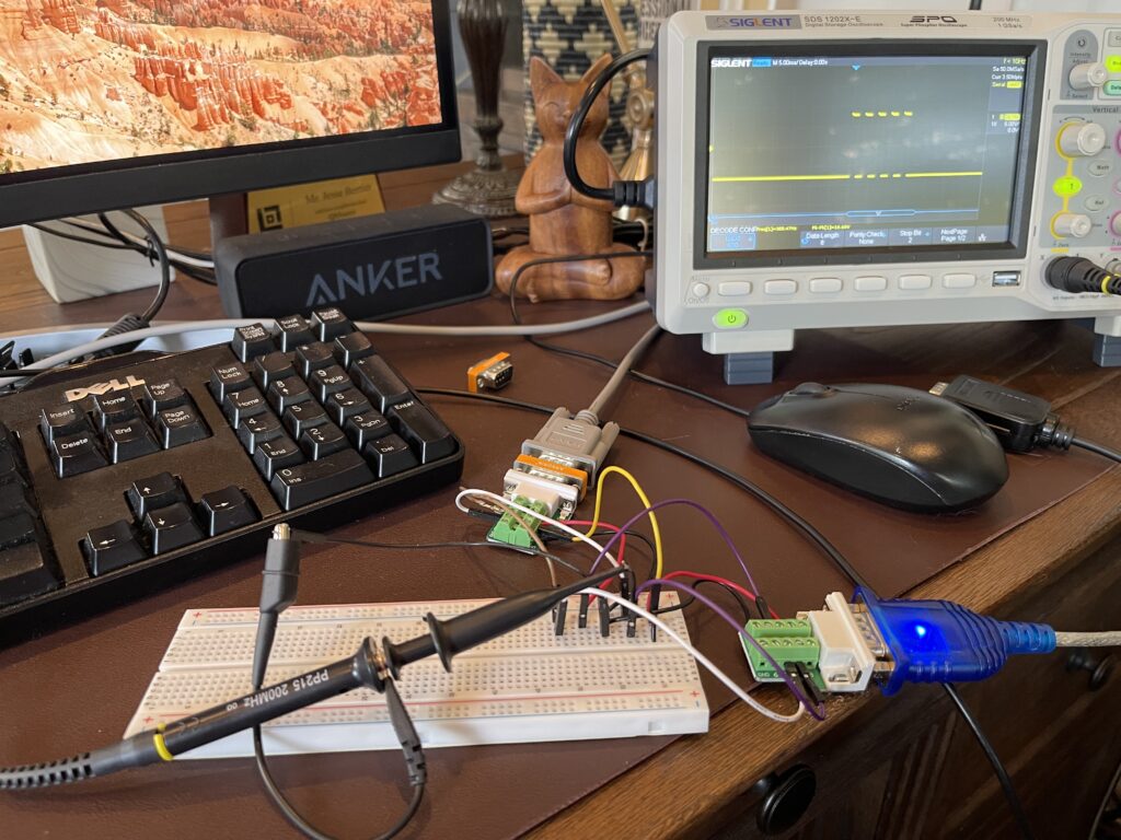
Since the PC-2 to the TP-10 connection did not work, I connected the PC-2 to my windows PC, with the same communication parameters (600,8,N,2). It worked, both ways. I was stumped as to why it worked with the PC but not the TP-10. So, I took out the scope and probed the TX line from the PC-2 into the TP-10:
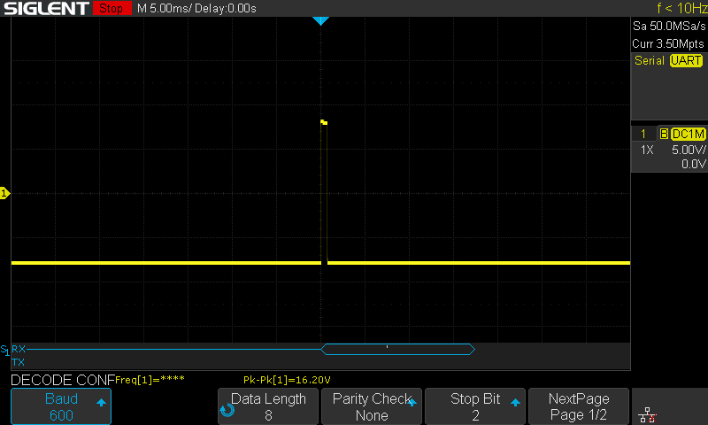
I saw this single bit no matter what key I pressed on the PC-2. I connected the PC-2 to the windows PC, and monitored a keypress on the PC-2.
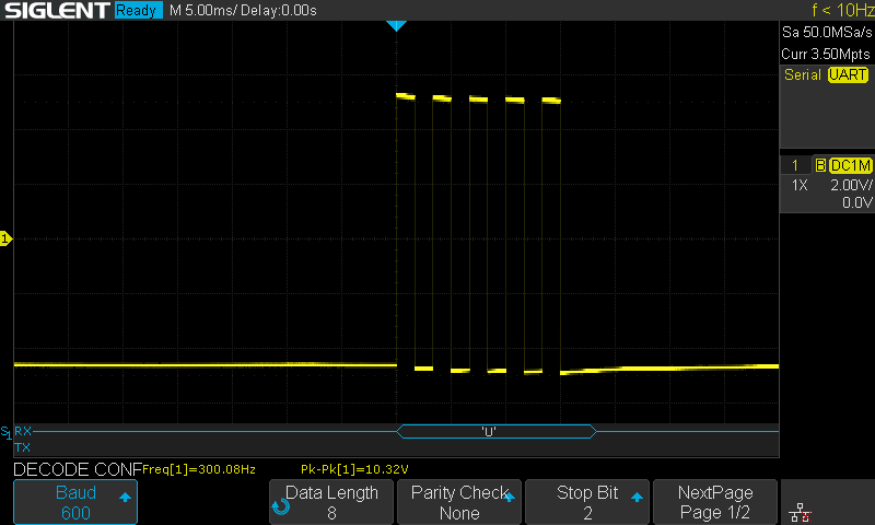
The PC-2 (similar to the Model 100 to the windows PC) worked as expected, and had a similar picture as above. The only difference in wiring between the PC-2 to the TP-10 and the PC-2 to the windows PC is all of the 9-pins of the DB9 connection are present and connected. The TP-10 DB9 connector I built had only the RX data, status and ground. More specifically, the status line (output) from the TP-10 was connected to the CTS input line on the PC-2.
Root Cause Discovered
After seeing the connection from the PC-2 work with the windows PC but not the TP-10, I had a theory as to why. Let’s start with the status line from the TP-10 and how it works:
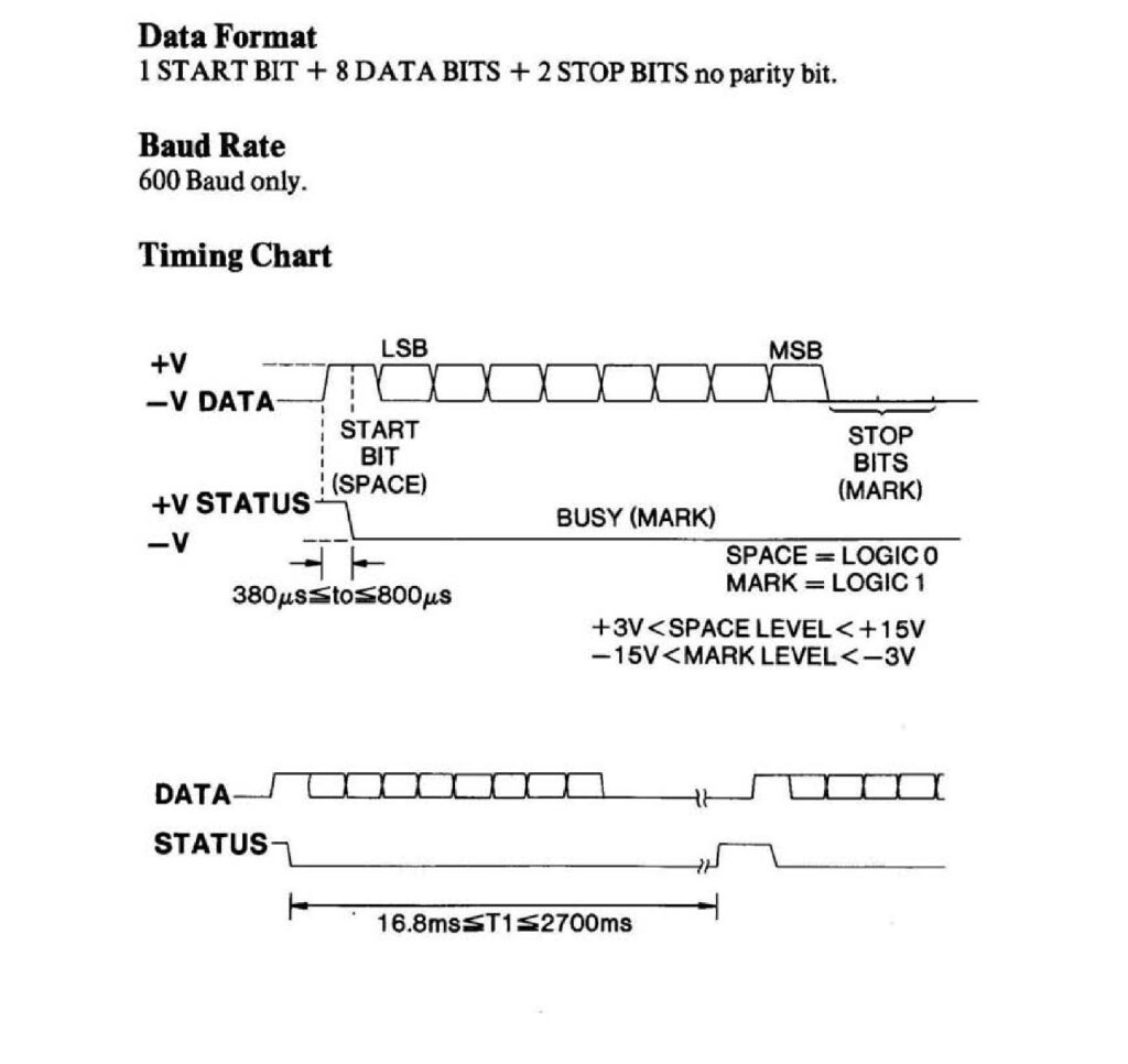
The TP-10 has a Status line, normally high, and is pulled low when it is not ready to receive a byte. I wrote about this being absolutely required for successful printing when connected the TP-10 to the Model 100.
Note that the status line is pulled low shortly after the start bit of the byte is received. I suspected this was the cause of the issue on the PC-2, as this line is connected to the CTS input line on the PC-2. I disconnected the status line from the CTS input on the PC-2, and nothing appeared to print on the TP-10.
I then theorized that the CTS line needs to be high on the PC-2 for it to transmit bytes over the wire. To prove this, I needed to pull the CTS input line high. I connected the DTR output line from the PC-2 to the CTS input line on the PC-2 (via the DB9 connector going to the TP-10). Instantly characters began to print correctly!
I did not realize that the PC-2 RS-232 not only supports hardware flow control, but requires it. The Model 100 does not nor does my windows PC by default. This is why the PC-2 started working when connected to the Model 100 or windows PC, but not when connected to the TP-10.
Further, because the TP-10’s status line is pulled low shortly after the start bit is received by the TP-10, the PC-2 stops transmitting immediately, in the middle of the byte being transmitted. Pulling the CTS line high and keeping it high was the workaround needed to get a byte out of the PC-2 when connected to the TP-10.
New Home Needed for the Status Line
Now that I know that the PC-2 needs to see the CTS line high in order to send data, I connected the DTR output from the PC-2 to the CTS input on the PC-2 to bypass the flow control in one direction. I can no longer use the CTS input on the PC-2 to monitor the status from the TP-10. I needed another input on the PC-2 to connect the status output from the TP-10 to. I ended up wiring the status line from the TP-10 to the DTR in on the PC-2.
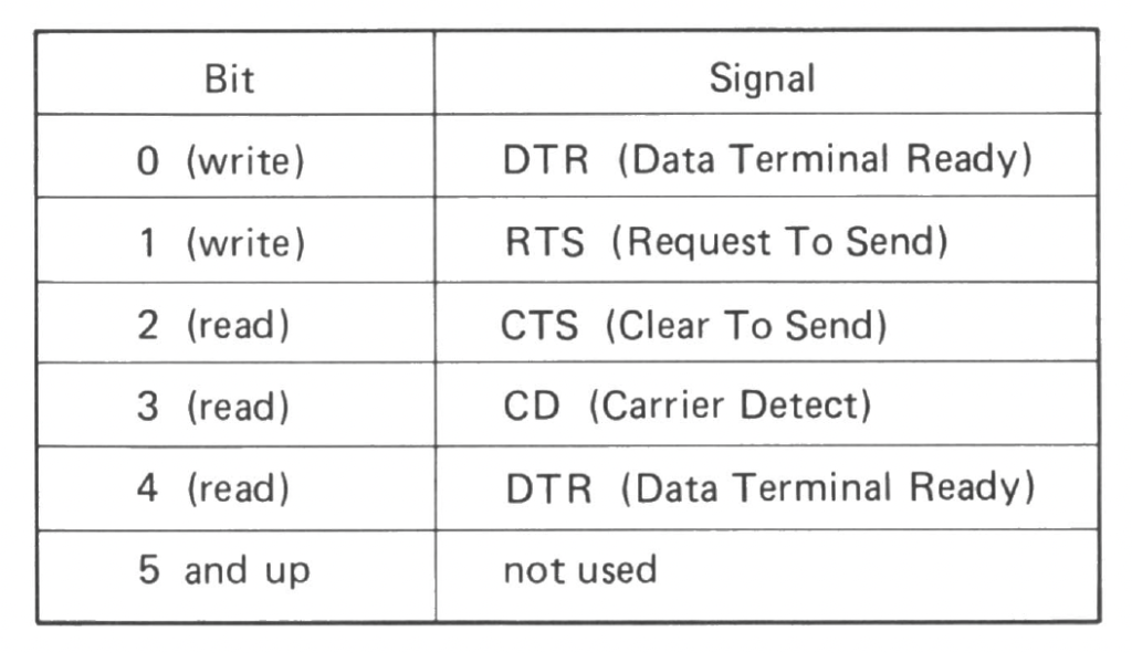
The PC-2 RS-232 module has the following I/O options:
Because of the changes needed to the wiring from the TP-10 to the PC-2, I chose to use the 2nd half of my DIN cable I bought from Amazon and use it for this project, rather than alter my Model-100 cable.
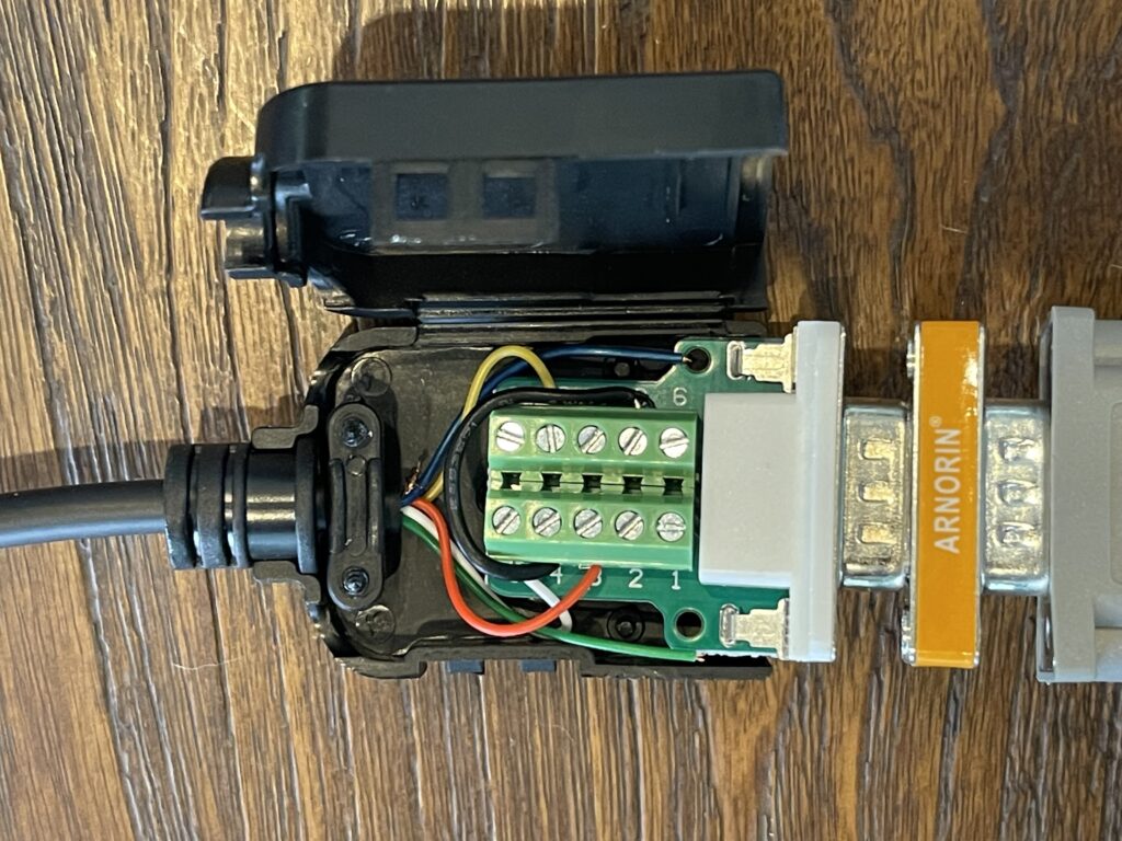
The final wiring that worked was:
TP-10 Pin 2 (Status) -> DB9 Pin 6 (DTR in)
TP-10 Pin 3 (GND)    -> DB9 Pin 5 (GND)
TP-10 Pin 4 (Data)   -> DB9 Pin 3 (TX Data)

DB9 Pin 8 (CTS In) <--> DB9 Pin 4 (DTR Out)
In order for my DTR output hack and DTR input signal to work, I used the following command:
OUTSTAT 0I was then able to read the status line from the TP-10 from bit 4:
O = INSTAT AND 16If O is 0, then the status line is high. If the status line is pulled low, O will be 16 (bit 4 set).
Finishing Touches for the Banner Program
After settling on a new input line for monitoring the status from the TP-10 and accounting for some variable differences with the PC-2, a new version of the banner program was complete.
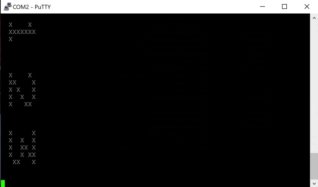
During the testing of the changes, I used PuTTY connected to the output of the PC-2 and sent ASCII characters over. This was to save on paper and time.
Final Thoughts
After successfully connecting and using the TP-10 thermal printer on the Model 100, I set out to use it wil the PC-2 and it was a success! It didn’t come without challenges, and was certainly worthwhile.
I suppose I could modify the Model 100 version to use the same input for the status line as I am now using on the PC-2. This would allow me to use the same cable for both computers. I could also optimize the BASIC program a bit more. Since the PC-2 has far more RAM than the PC-8, I didn’t focus as much on the memory usage.
In order to use this printer or any other serial device on the PC-2, you will need the RS-232 adapter, which is hard to find. However, perhaps in the near future, Jeff Birt will offer a modern equivalent to this module. This project is described in his You Tube post.
It is possible to redirect I/O on the PC-2 to a device on the RS-232 port, such as the TP-10 printer – several options are possible, such as keyboard and LCD mirroring. This effectively provides similar printer options as the built-in plotter on the printer/cassette module.
Program Listing
Below is a link to the banner program in ASCII format. Use the commands below to send, and CoolTerm can be used. Be sure to set a transmit line delay of 500ms, with 0D as the delay character. This causes CoolTerm to pause 500ms after each carriage return (0x0D).
SETCOM 2400,8,N,1
SETDEV CI
CLOADa
Note: Do not send LF characters to the PC-2, only CR at the end of each line. If sending a file you have created or modified, use a program such as Notepad++ to remove all LF characters before sending to the PC-2. Also, be sure to include a line with a CR by itself at the end of the file. This signals the PC-2 that the transfer is complete.
Below is the listing for the banner program. This version reads the character bitmap data from ROM. Note the REM statements should be ignored or removed.
LCD 5x7 FONT IN ROM STARTS AT 0xFD45

INIT AND LOOP THROUGH EACH CHAR IN STRING TO PRINT FOR BANNER

100 CLEAR : SETCOM 600,8,N,2 : OUTSTAT 0 : DIM Z$(2) * 32
110 X$ = CHR$(143) + CHR$(159) : X$ = X$ + X$
120 Y$ = CHR$(128) + CHR$(144) : Y$ = Y$ + Y$
125 P$ = CHR$(13)
130 INPUT “Banner Text?”;T$
140 PRINT#-8,CHR$(26);
150 L = LEN(T$)
160 FOR C = 1 TO L

READ TO LOCATION IN DATA ARRAY FOR CURRENT CHAR BITMAP

170 E$ = MID$(T$,C,1)
180 K = ASC(E$) : A = &FD45
190 A = A + ((K - 65) * 5)
200 B = PEEK(A)

READ EACH ROW IN BITMAP FOR THIS CHAR

300 FOR D = 1 TO 5
305 Z$(0) = "" : Z$(1) = "" : G = 8
310 FOR F = 1 TO 4
320 H = B AND G : IF H = 0 THEN GOTO 340
330 Z$(1) = Z$(1) + X$ : GOTO 350
340 Z$(1) = Z$(1) + Y$
350 H = B AND 16 * G : IF H = 0 THEN GOTO 370
360 Z$(0) = Z$(0) + X$ : GOTO 380
370 Z$(0) = Z$(0) + Y$
380 G = G / 2 : NEXT F

PRINT THIS LINE TO PRINTER

400 GOSUB 450 : GOSUB 450 : GOSUB 450
410 A = A + 1 : B = PEEK(A) : NEXT D
420 Z$(2) = P$ + P$ : GOSUB 500
425 NEXT C
430 END

PRINT BOTH PARTS OF OUR LONG LINE

450 Z$(2) = Z$(0) : GOSUB 500
460 Z$(2) = Z$(1) : GOSUB 500
470 Z$(2) = P$ : GOSUB 500
480 RETURN

STRING TO PRINT IS Z$(2), ONE CHAR AT A TIME, THEN CR/LF CONTROL CHAR TO PRINTER

500 M = LEN(Z$(2))
510 FOR N = 1 TO M
520 PRINT#-8,MID$(Z$(2),N,1);
527 GOSUB 600
530 NEXT N
560 GOSUB 600
570 RETURN

READ DTR BIT AND RETURN WHEN LOW (INVERTED)

600 O = 0 : O = INSTAT AND 16
610 IF O = 0 THEN RETURN
620 GOTO 600
Note: Line 600 has an intentional delay before reading the status lines on the RS-232 port. This speeds up the printing a bit, avoiding the case where the first read is still busy.
Note: If you wish to connect the PC-2 to a terminal to “test” the banner program, add the following line:
126 X$="X" : Y$=" " : P$=CHR$(10) + CHR$(13)And change line 400:
400 GOSUB 450 You can then see the output on your terminal for testing characters for example: