

TRS-80 Model 100
I recently opened up a box where I had kept my old calculators (TI and Radio Shack) and I recently restored a Sharp CE-150 printer cassette interface for the PC-1500 / PC-2. I had been searching eBay for plotter parts and kept seeing postings for the TRS-80 Model 100.
I remember seeing this portable computer in the Radio Shack catalogs back in the 1980’s. I had never seen one in person, but I do remember they were seemingly around for awhile, and seeing them abundantly available on eBay piqued my interest.
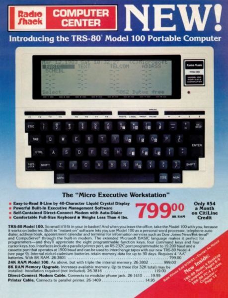
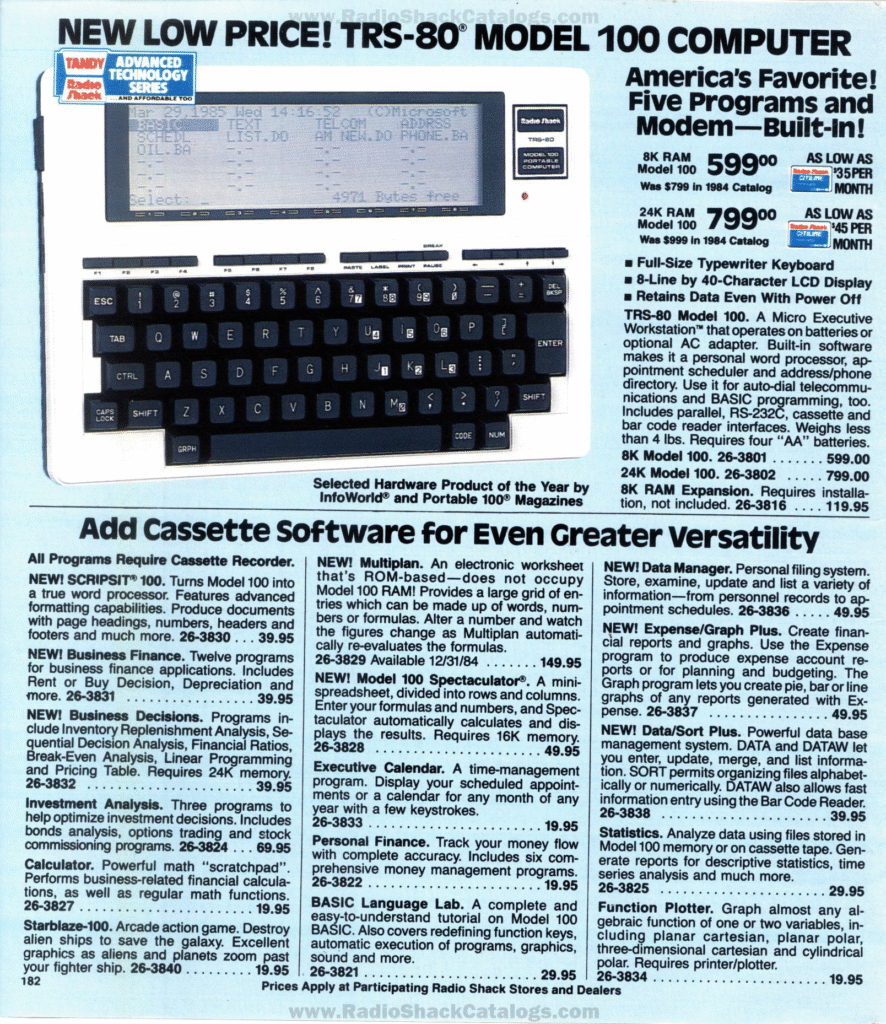
The Model 100 first appeared in the 1984 Radio Shack catalog on the back cover:
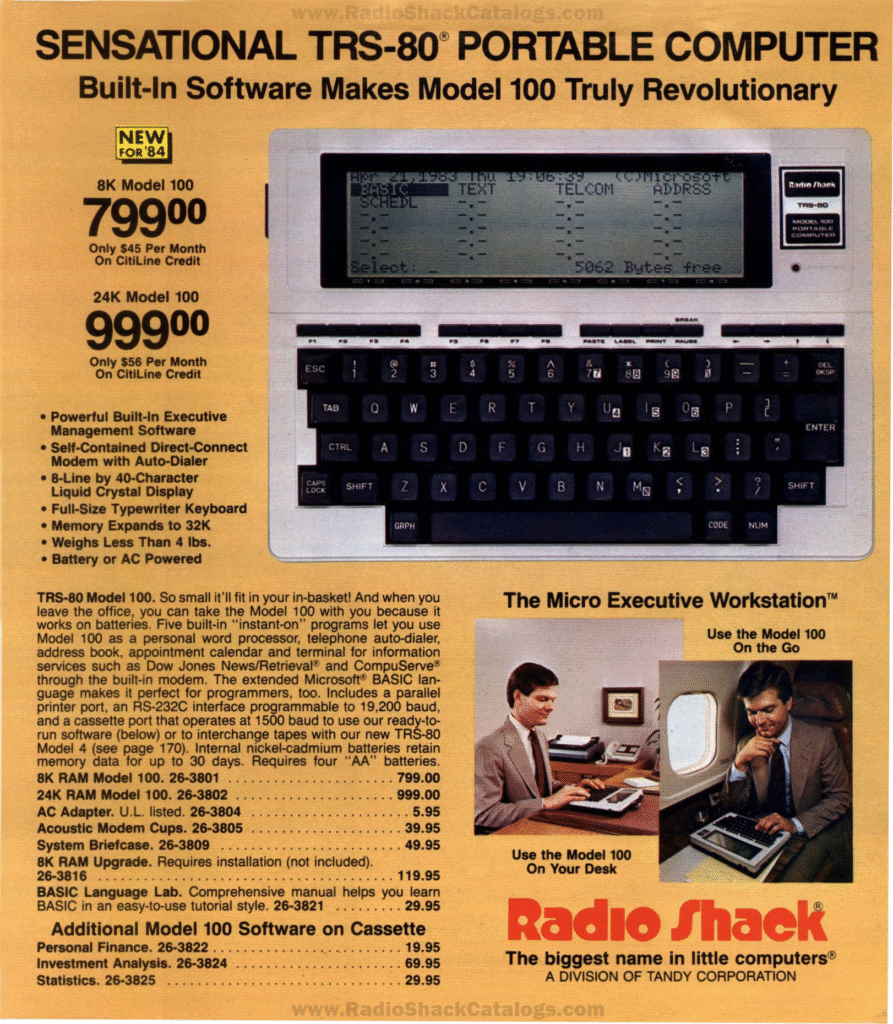
In the 1986 Radio Shack catalog, a 24 KB Model 100 was listed for $799, since the Model 200 had been released. The Model 100 disappeared by the time the 1987 catalog was released, as the Model 102 was introduced that year for just $499.
Screen
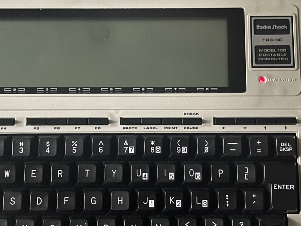
The Model 100 has a multi-line LCD display with an adjustable contrast. The contrast control is on the right side of the unit and allows for various viewing angles. The LCD is dot addressable, and the characters are 5 x 8 pixels.
The display is 40 columns wide by 8 lines. In pixels, the LCD is 240 x 64. There is a row of soft keys below the display, labelled F1 – F8, along with labelled hotkeys: paste, label, print, break/pause, followed by four arrow keys.
The multi-line display allows for very easy and convenient editing of programs, using spreadsheets, word processing, a terminal interface, and much more.
Keyboard
The Model 100 has a full size keyboard. The keys are full travel, have excellent response, and are very easy to use. There is a caps lock, number lock, and graph/code keys allowing for quick access to extended ASCII characters.
Batteries
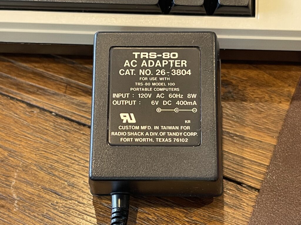
The Model 100 runs on 4 “AA” size batteries or via a 6 volt DC adapter. On battery power, the Model 100 boasts about 20 hour battery life on 4 “AA” batteries.
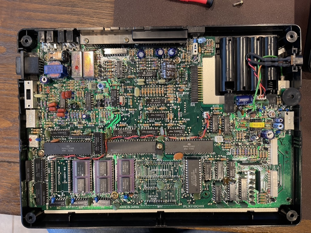
There is also a built-in NiCd battery on the main PCB for keeping memory contents intact when changing the “AA” batteries or when unplugged from a power source. Because the programs and data are stored in RAM, the contents would be lost without this battery or a steady power supply, either from the wall adapter or “AA” batteries.
The NiCd battery is recharged when the unit is supplied with a power source.
The AC adapter is 6 volts at 400mA, center negative. There is a low battery light on the front of the Model 100 which indicates when it is time to change the “AA” batteries.
Popularity and Commercial Success
The Model 100 is often referred to as the “Model T” because it is known to be the first commercially successful laptop (or one of the first). It was quite successful for Tandy / Radio Shack and allegedly they produced about 6 million of these units. This is one of the reasons why there are so many to be found on auction sites to this day.
Memory
There were two versions of the Model 100 released, an 8 KB and a 24 KB version. Either unit could be expanded to up to 32 KB of RAM using 8 KB memory modules.
The RAM was used not only for running programs (BASIC or assembly), but it was also used as a basic file system to store programs, documents, and data files. This is much like the Casio PB-1000 and PB-2000 which would be released years later.
The 24 KB version has three 8 KB RAM modules installed, leaving one remaining socket for another 8 KB of RAM. I added an 8 KB RAM module to the one I had acquired.
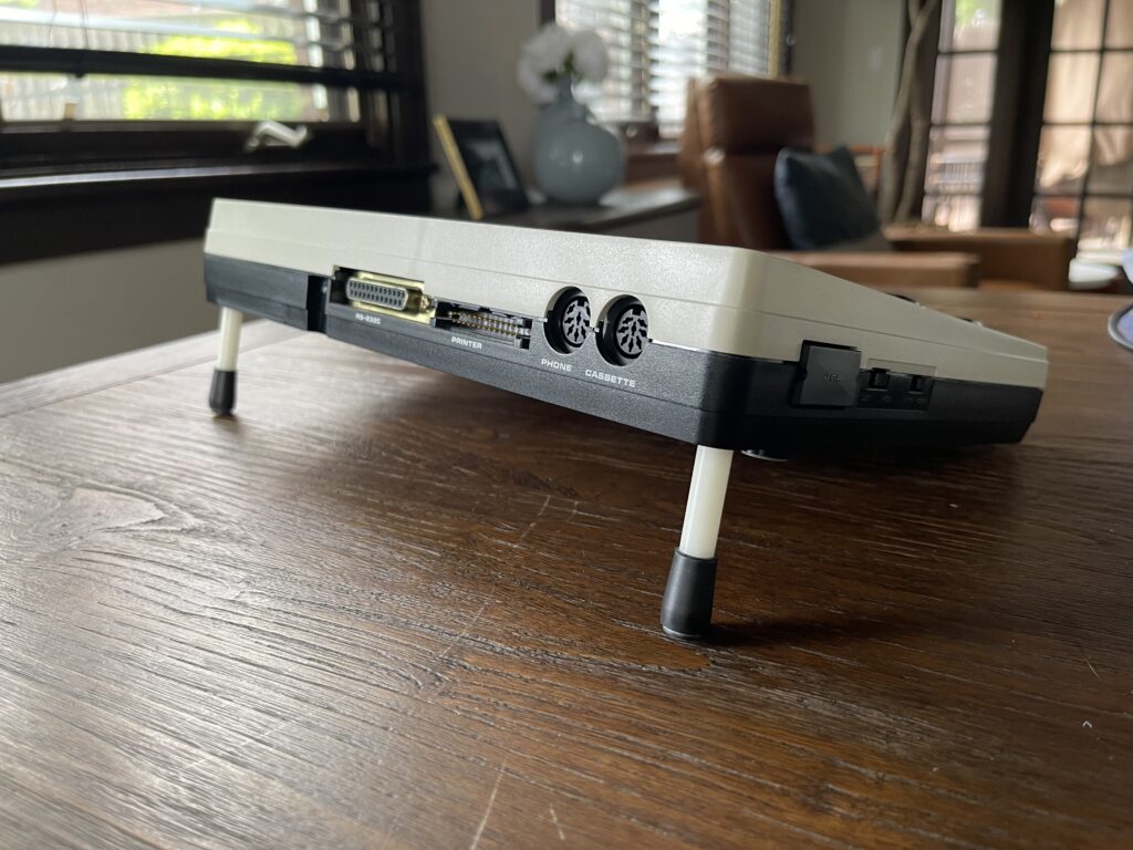
Ports
The model 100 has both a parallel port and a serial port (RS-232). The parallel port can be used to connect to printers and plotters.
The parallel port is not a Centronics connector, but is an IDC type connector which is used with ribbon cable. An example of a parallel IDC to Centronics cable is shown below:
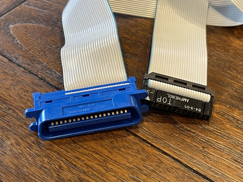
The RS-232 port can be used to connect to external disk drives, printers, modems, TNCs, PCs or other Model 100’s. The RS-232 port can support baud rates up to 19,200 baud.
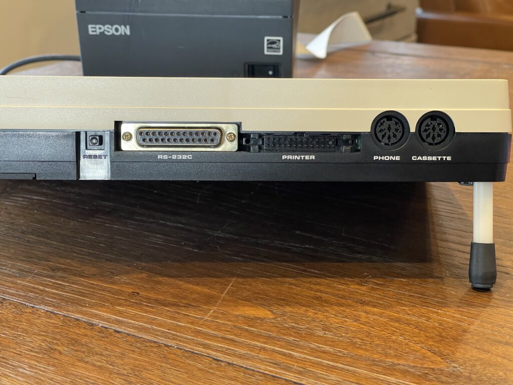
Radio Shack sold plastic stands for $3.99 which held the Model 100 up on a slant for easier typing and screen viewing when using on a desk. One of these stands can be seen in the photo above, on the far right side.
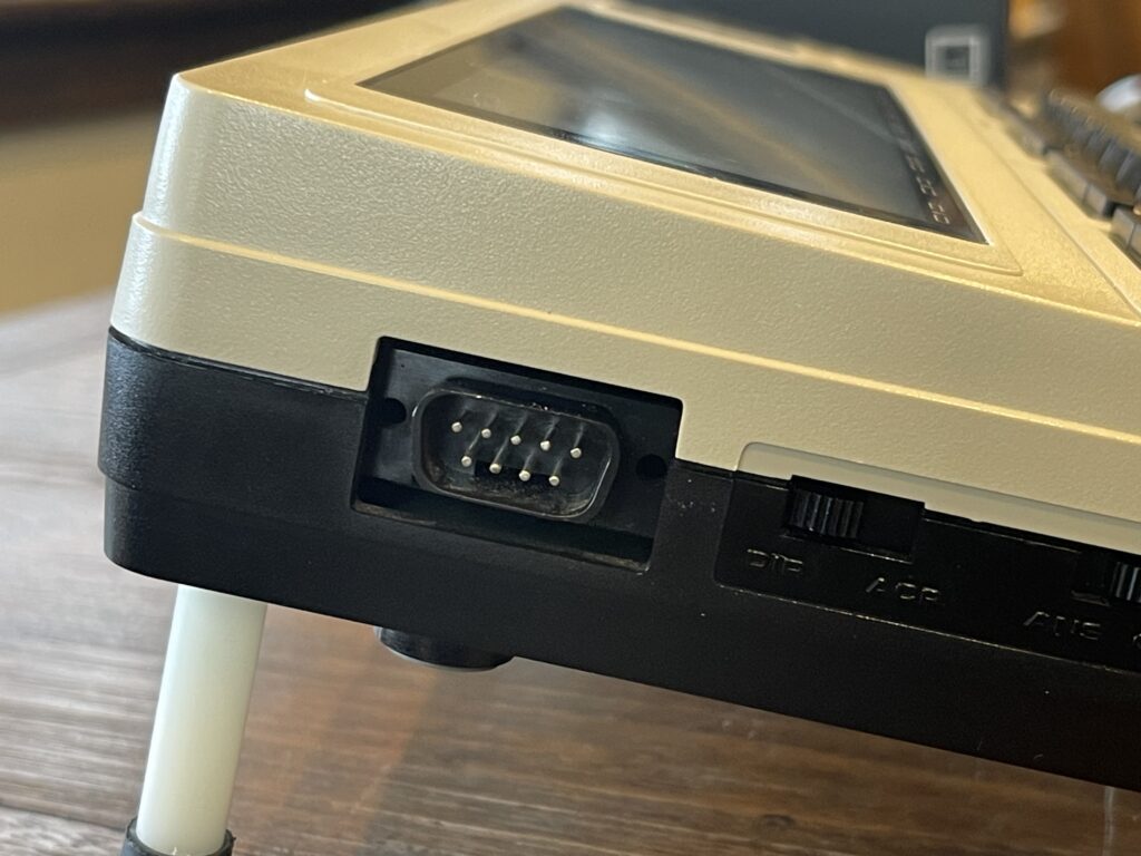
There is also a built-in 300 baud modem, accessible via a DIN style port which is used to connect to a telephone line. There is a DIN to modular plug adapter which is needed to connect the modem to the telephone line.
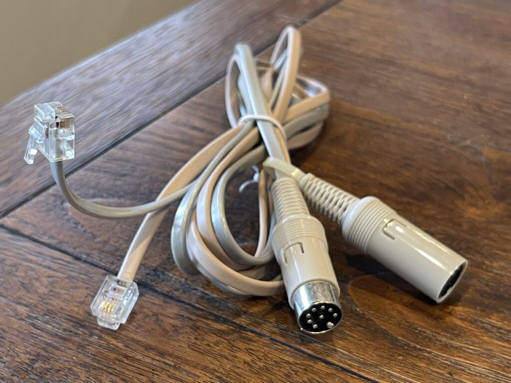
Notice there is a “shorting plug” included with the telephone line adapter. This plug allows this telephone line adapter to remain connected between the telephone and the jack when not in use. The user guide states that the beige line connects to the jack while the silver line connects to the telephone.
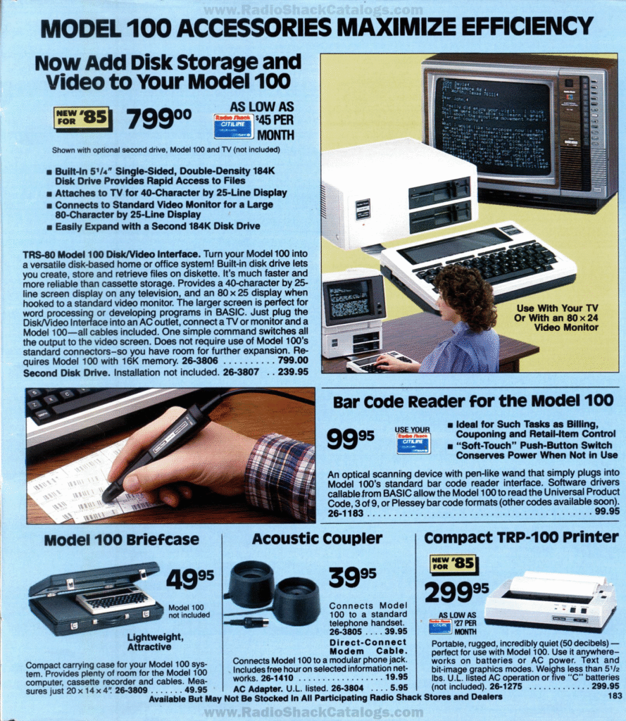
There was also an acoustic coupler accessory that was available which plugged into the same DIN jack in the Model 100, which could be used for accessing main frames or dial up services via a pay phone. An image of the acoustic coupler can be seen in the accessory page from the 1984 Radio Shack catalog below:
Cassette Port
There is also a cassette interface port which can be used to load and save programs. In order to test this port, I could have used any standard cassette recorder or a PC. However, I had my eye on a matching recorder for awhile, and found a good price on one on eBay.
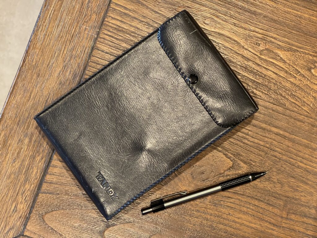
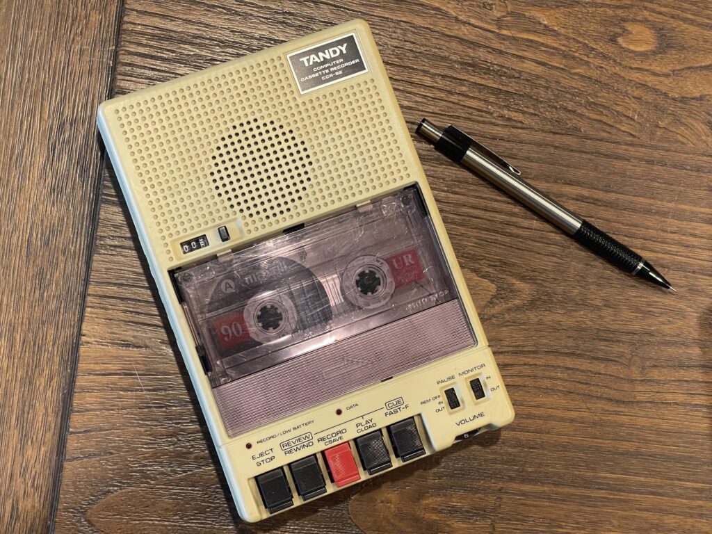
The CCR-82 was introduced in 1985 (one year after the Model 100) and is quite a bit smaller than the standard shoe box style recorder. It comes with a case very similar to the Model 100 case, and appears to be the matching accessory for the Model 100.
Based on the price, I fully expected the recorder to not work when it arrived, and that was indeed the case. Luckily all it needed was 3 new belts. I was able to determine this by seeing the take up wheel was moving a bit after pressing the play button, and the audio amplifier appeared to work.
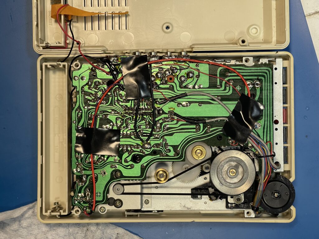
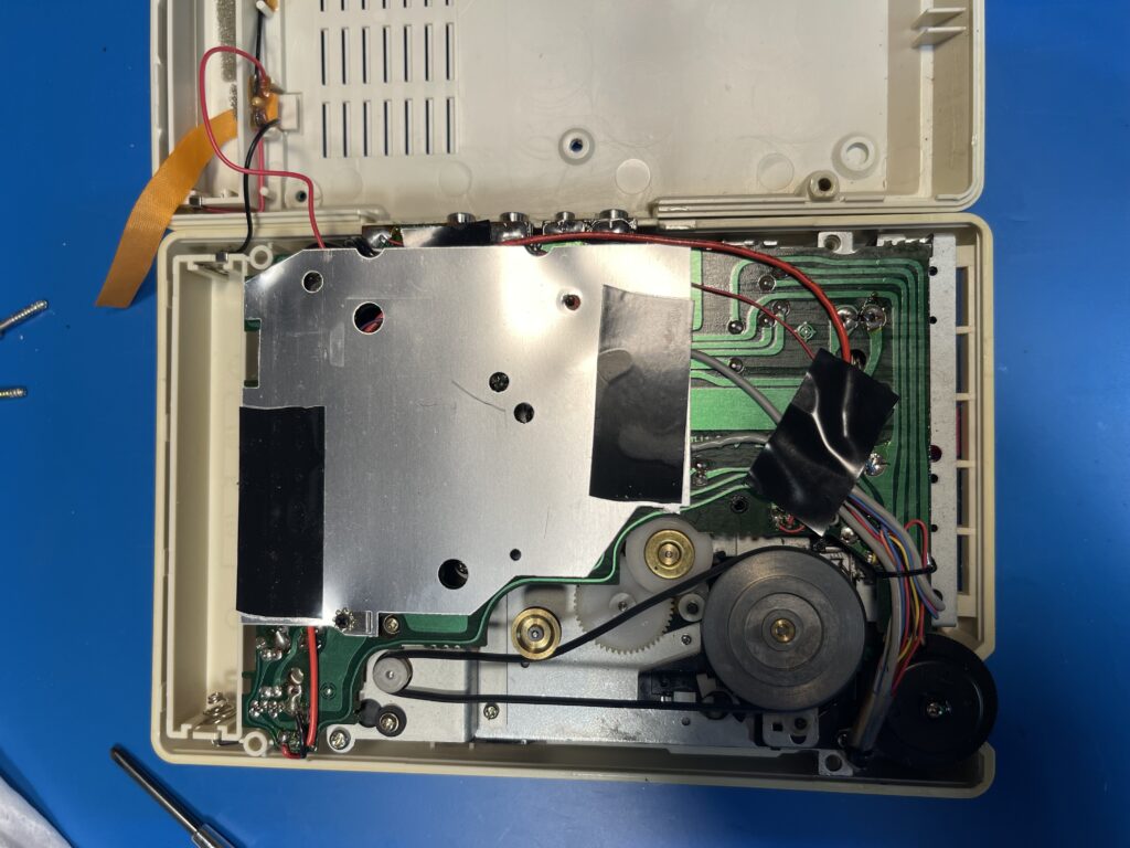
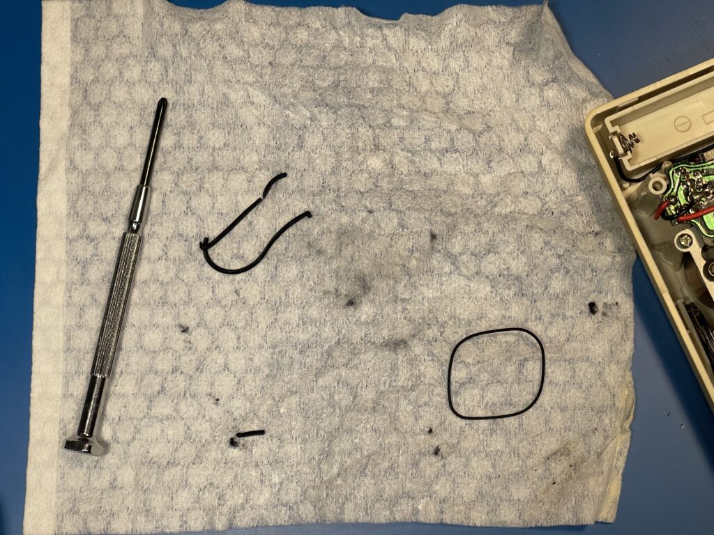
I have quite a few new belts in various sizes from fixing other cassette recorders and players, and this model actually needed 3 belts (instead of the usual 2 belts). There were two more belts underneath the PCB. One for the cassette wheels and another for the tape counter.
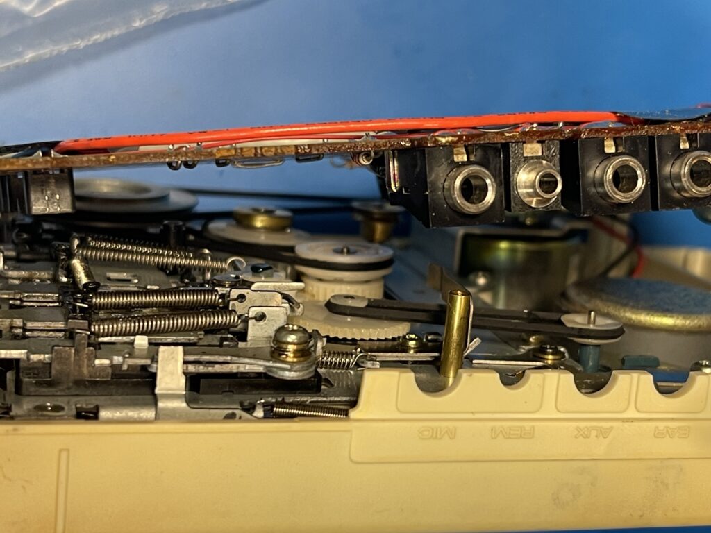
The belt for the wheels was completely disintegrated, and the other two were well on their way to the same fate.
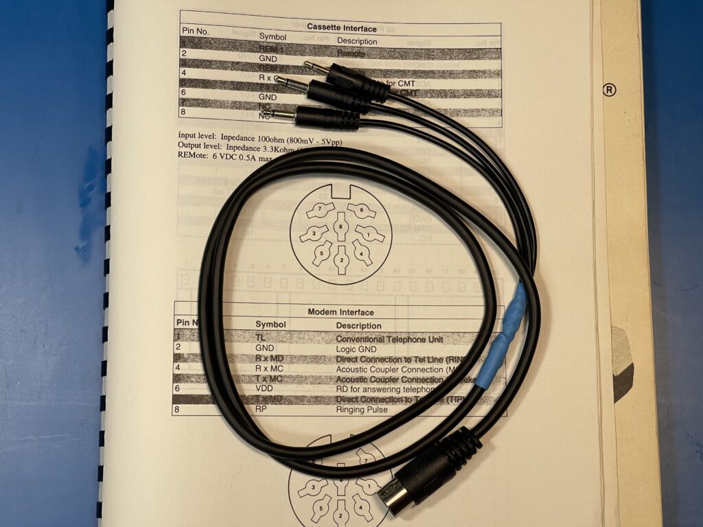
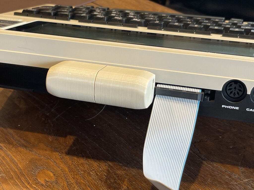
After replacing all 3 belts, I proceeded to build a cable for the cassette port on the Model 100. The port uses a standard MIDI style DIN connector (the same as the Casio FX-880P pocket computer and several other vintage computers). Of course the pinout was different than any of the existing cables I had already made.
I buy the DIN cables on Amazon and then cut the cable in half, giving me two cables with the DIN connector to work with. I then do the same with the 2.5mm and 3.5mm audio connectors as well. The Model 100 Owner’s Manual included the pinouts on this interface as well as the others, which was convenient.
After building the cable and testing it, I found that it worked on the first try! I am usually not that lucky.
I found that the baud rate for this interface is much faster than the baud rate on the pocket computers I have experience with. Usually the pocket computers, at least the older ones, worked at 300 baud.
The initial tests worked well and I found that I needed to adjust the volume on the CCR-82 to about a level of 6 in order to avoid the dreaded I/O error when attempting to load a BASIC program from cassette.
Now that the CCR-82 is back in operational condition, I can use it with pocket computers and other vintage computers. It has some advantages over a standard cassette recorder for use with computers, such as input and output level indicator (LED), monitor, remote enable & disable, and cue & review control. It runs on 4 “AA” size batteries and can use the same 6V AC adapter the Model 100 uses.
The CCR-82 Service Manual is linked below for reference:
BCR Port
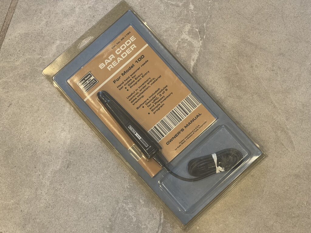
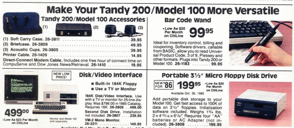
Lastly, there is a BCR port on the left side of the Model 100. This port was originally designed to be used with a Bar Code Reader, available as an accessory:
Like most Radio Shack software distributed for the Model 100, the Bar Code Reader software was distributed on cassette. I have included the programs and drivers below:
ROM and System Bus Connectors
The bottom of the Model 100 has the battery compartment and ROM / bus connector:
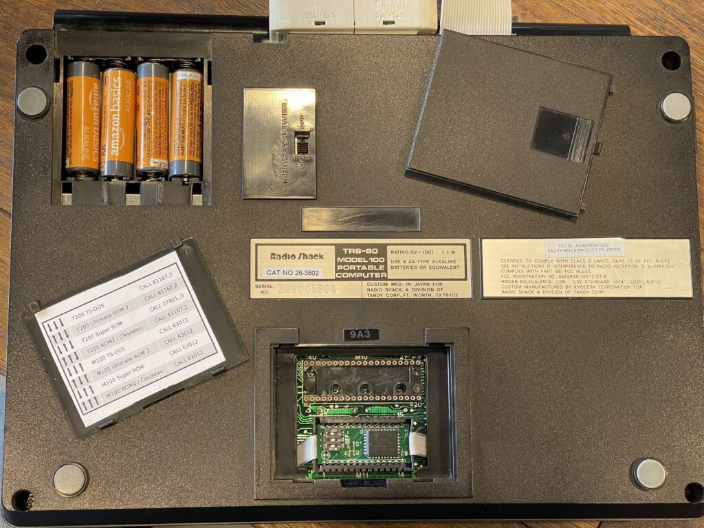
The ROM & bus connector are exposed by removing the cover. There were some ROMs sold commercially, and these days hobbyists have included several ROMs on a single board, selectable either by a rotary dial or dip switches. Included with many ROMs is a sticker that indicates the addresses in memory where you can call to hook into the start up routine to invoke each program or subroutine included in the ROM.
There is a memory power switch on the bottom as well, which disconnects the NiCd memory backup battery, allowing the memory contents to not be backed up on power loss. This is intended for disconnecting the backup battery when storing the Model 100 for long periods of time without normal use.
Programming Support
Not only is the Model 100 capable of running BASIC programs, it can also run 8085 assembly programs. The BASIC support is decent, supporting bitwise operators, random number generation, interaction with the real-time clock, basic sound support, LCD operations, peripheral support, and much more.
Assembly programs include not only the included applications built into the ROM, but third party ROMs and there are assemblers which run on the Model 100 itself available as well.
There are quite a few subroutines in ROM which are useful and can be invoked using the CALL function in BASIC. The argument to this function is the address in memory for the subroutine. For example:
CALL 27967,13The second argument, optional, would be the argument to pass to the A register, if the subroutine expects an input for example.
Disk Video Interface
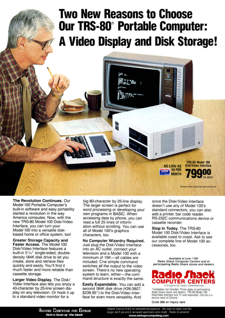
Tandy released the disk video interface, or DVI, for the Model 100. This unit would allow for a 40 or 80 column TV display output and up to two 5.25″ floppy disks. This would effectively transform the Model 100 into a desktop computer.
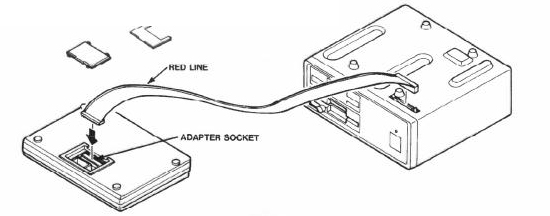
The DVI would plug into the bus port on the back of the Model 100 as shown in the illustration above. I seriously doubt that removing and plugging in this adapter many times would survive in the long run. Not only was this not a “hot swappable” accessory, it cost $799, which at the time was the same cost as a 24 KB Model 100 itself.
The following year, in 1986, Radio Shack dropped the price of the DVI to $499.
The DVI requires at least 16 KB, which means it cannot be used with the base 8 KB Model 100.
Portable Disk Drives
Tandy released a portable 3.5″ disk drive (TPDD) for the Model 100. This drive connected to the RS-232 port and required using the included FLOPPY.CO program or TS-DOS to read and write using the drive.
The ROM for the drive included a method to push the bootstrap to the Model 100, then the loader for the FLOPPY.CO would pull the image from the drive itself. Once the drive access program is loaded into memory in the Model 100, it can be run at any time. The bootstrap process would only be required if the program were to be deleted from the Model 100 or if the Model 100 was factory reset.
The drive used “AA” batteries or a power adapter.
Tandy released the portable disk drive 2 afterwards, otherwise known as the TPDD2.
It should be noted that there is not really direct disk access from the Model 100, access to the disks is via commands over the RS-232 port. This is what the FLOPPY.CO or TS-DOS would use to transfer files to and from the drive. The drive acts more like a back-up solution, where you can copy files from the drive to the Model 100 and vice-versa.
There is expanded BASIC support for “direct” disk access (via RS-232 using the TPDD protocol) if TS-DOS is loaded in memory.
The communication format that the TPDD and TPDD2 drives use is often referred to as the TPDD protocol.
Buzzer
The Model 100 has a built-in buzzer which can be used for varying pitch and duration.
Built-In Applications
The Model 100 has a few built-in applications included in the system ROM. Each of these can be accessed from the main menu.
- A BASIC editor can be accessed from the main menu.
- A text editor, which provides basic word processing and printing of text files.
- A terminal program, called TELCOM which provides basic terminal functions.
- An address book
- A scheduler
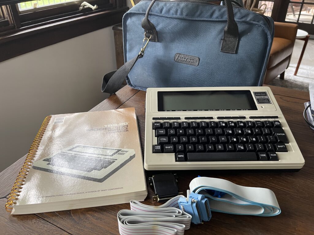
Owners Manual
The Model 100 came with a spiral bound owner’s manual and a quick reference guide.
The Owners Manual is linked below:
The Quick Reference Guide is linked below:
The Technical Reference Manual is linked below:
Sourcing a Model 100 from eBay
I searched through many postings on eBay for a Model 100. There is quite a difference in price between postings. Some had all of the accessories included and claimed a fully working unit. Others would have none of the accessories and note “parts only” or repair.
There are still many units available on auction sites due to the large volume of Model 100’s manufactured. Since these were relatively well built, quite a few survived over the decades.
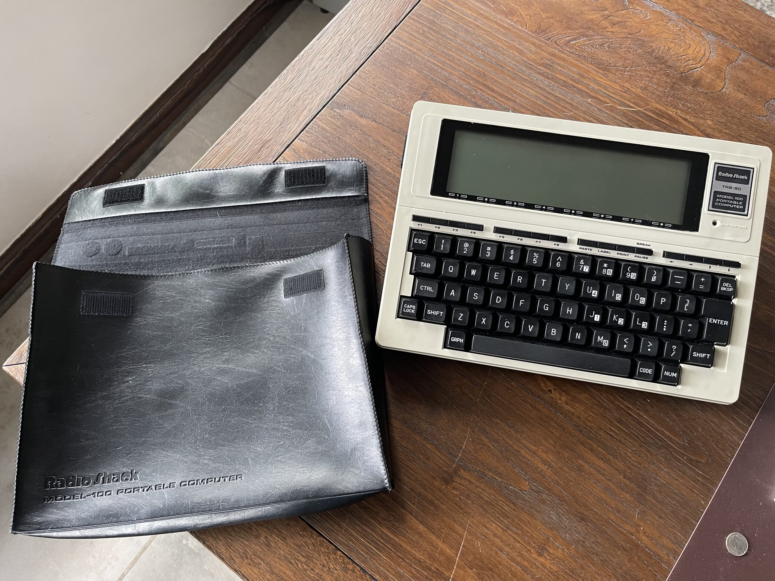
I was interested in a working unit and one which had the accessories. Specifically the soft case, parallel port cable, AC adapter, and owners manual. I was careful to inspect the photos for leaking AA battery damage, screen damage and general appearance. I was interested in the Model 100, not the Model 102 or the successors.
I was lucky to find a Model 100 24 KB version with all of the accessories and a carry case. The condition was excellent and it did in fact work when I put batteries in it.
Typical Issues with Age
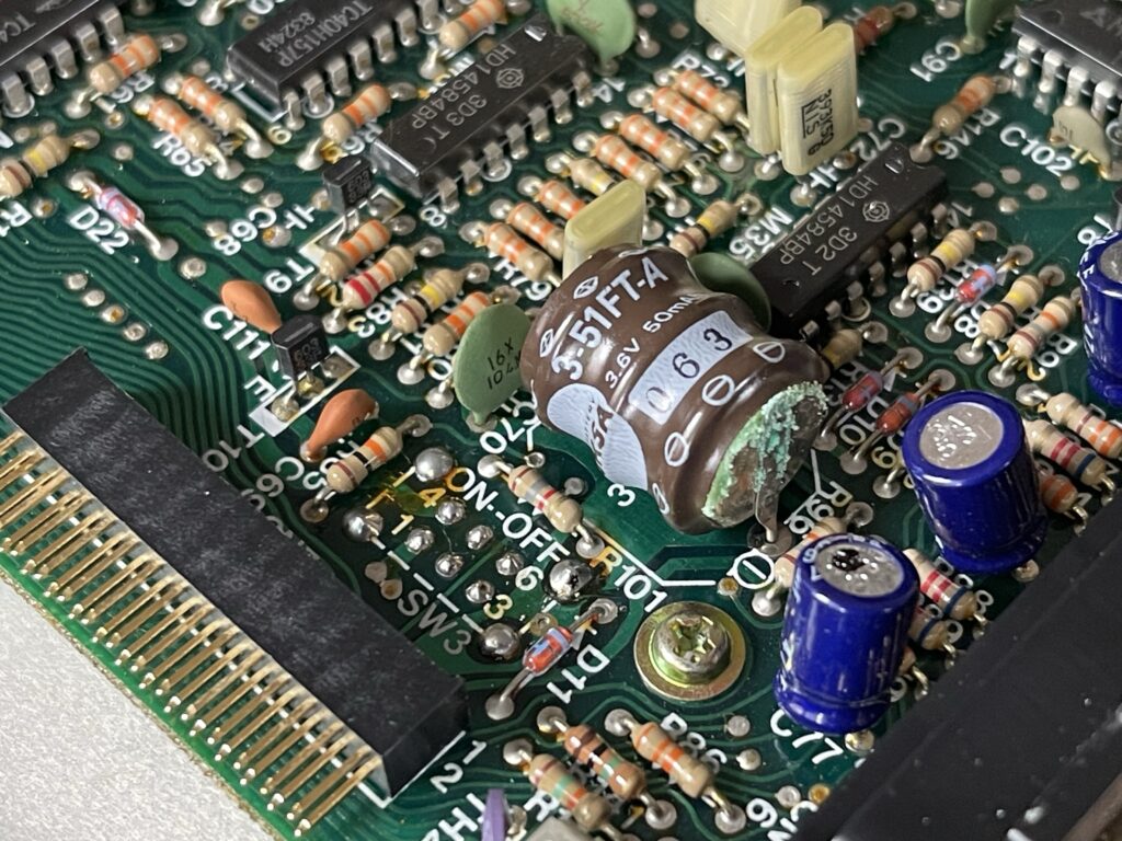
As with most vintage electronics, there are some components which do not survive the test of time. For example, internal battery packs and electrolytic capacitors can leak over time. In the case of the Model 100, the internal RAM backup battery is NiCd and is known to leak. When it does, it can cause quite a bit of damage to the PCB and/or nearby components. When electrolytic capacitors leak, they can fail open or short, damaging other components or cause erratic operation.
Sometimes “AA” batteries are left inside the unit and those too will eventually leak.
Initial Assessment
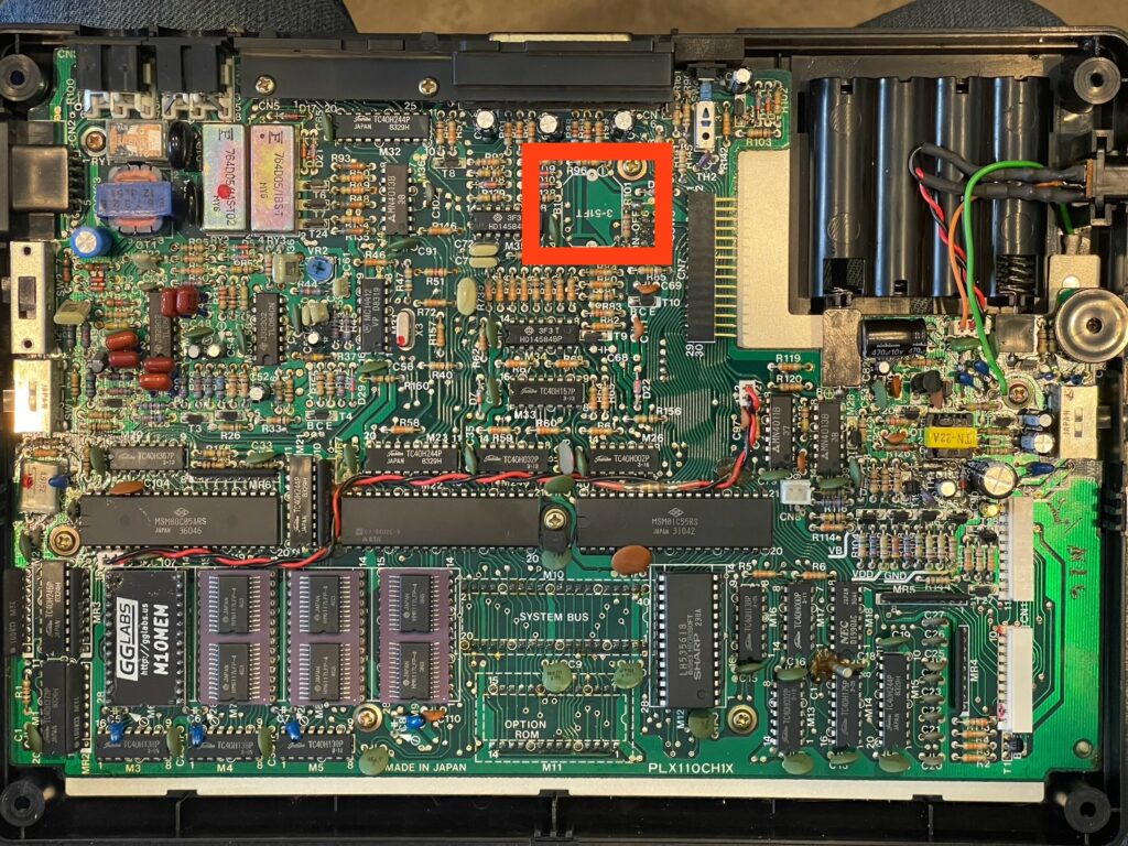
My unit had a NiCd pack that had just started to leak, but not yet reached the PCB. It had some minor corrosion in the AA battery compartment. I removed the original NiCd backup battery and replaced it.
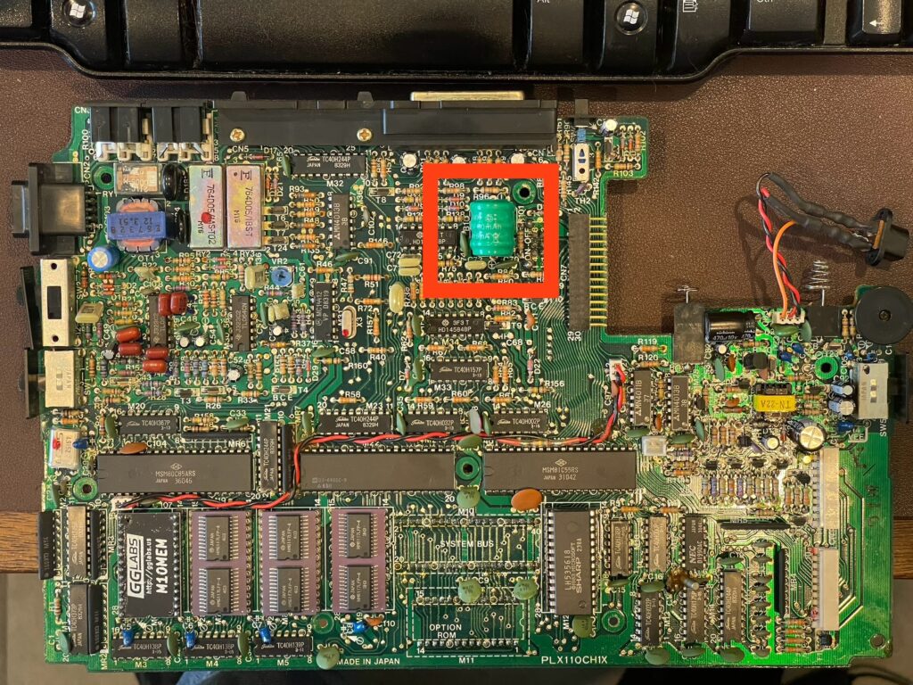
I replaced this battery backup because I did not want to risk losing my programs or data if the “AA” batteries are removed. Of course I could back up and restore my data, but that process is not ideal and it is a bit time consuming.
I was able to get an exact replacement here, from Jeff Birt.
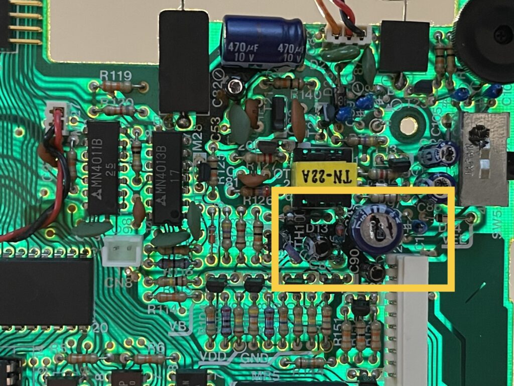
Not only had the NiCd battery started to leak and need replacement, upon further inspection, I noticed many of the electrolytic capacitors had leaked and needed to be replaced.
As with any vintage gear, a decision on whether to proceed with a repair is based on nostalgic value of the item and cost and effort to repair. After all, we really never know how much effort will be needed. For example, replacing a single part might be all that is needed to bring something back to working order. On the other hand, it could be several parts and hours of troubleshooting.
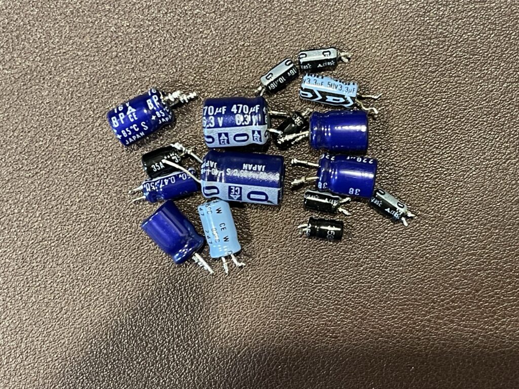
I decided to replace the electrolytic capacitors and then evaluate from there. Since the parts cost was under $20 with shipping, it was not an expensive attempt to undergo.
Sourcing the Parts
I ordered replacement capacitors from Mouser Electronics and was fortunate to have an excellent guide prepared by Jeff Birt for the replacement part numbers. This made it easy for me to not have to measure the lead spacing and verify sizes.
Some of these capacitors were non-polarized. The schematics and parts list in the Model 100 service manual were helpful in verifying the correct replacement parts.
Two of the capacitors on Jeff’s list were not currently available from Mouser, so I substituted similar ones. Note that non polarized capacitors will work where a polarized capacitor was, but not the reverse. If you can find only a non-polarized equivalent, it can be used in place of the polarized capacitor. It is simply a bit more expensive than the non-polarized option.
Experience Needed or Gained
Recapping a PCB can be challenging if you do not have experience. I had never done this before, but I did have soldering experience. The challenge here is to be able to remove the old capacitor without damaging traces or the PCB. This requires the right balance of heat and technique for extraction.
At first I struggled to remove the first few caps. This was because I was using the wrong soldering tip. The tip I was using was the one I use to solder small components onto small PCBs. The heat from the iron was not transferred efficiently to the pads where the capacitor was soldered into. Adding more heat (raising the temperature on the iron) did not really help. The result ended up being that while the solder was melted on the pad, it was not enough transfer of heat to run through the component lead to the other side of the board.
I changed the soldering iron tip to a small wedge style tip, which immediately worked to not only melt the solder on the back of the board, the heat instantly transferred all the way through the component lead to the other side of the board.
For the capacitors which had narrow lead spacing, I was able to use the wedge tip to heat both leads at the same time while gently pulling on the capacitor from the other side of the PCB. The end result was a few seconds with the iron and the cap was removed quickly.
For the capacitors that had greater lead spacing, I simply heated one leg at a time, alternating between the two, rocking the cap back and forth, allowing for incremental raising up of each leg of the cap until it was completely free of the PCB.
After removal of the old capacitor, any remaining solder in the through hole needs to be removed or opened up enough to place the new capacitor in. I ended up finding that solder wick worked very well for this. I do have a desoldering iron, but I decided not to use it. I did not want to risk using too much heat on this PCB and damage traces or pads. My particular desoldering iron does not have a temperature control on it.
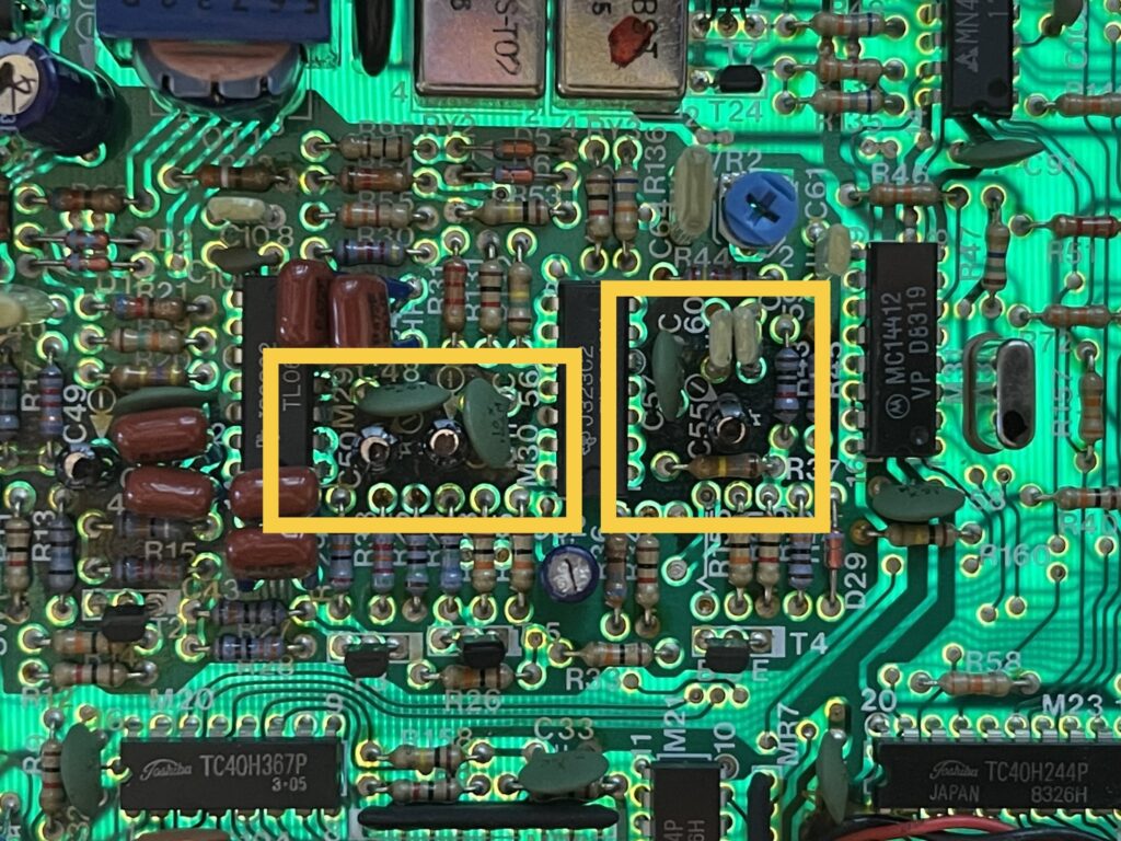
Damage from Leaking Capacitors
The electrolyte from the electrolytic capacitors had leaked out of about half of the capacitors on the PCB. When it leaks, it tends to work its way under the solder mask and along the copper traces in the board. Visually you can see dark spots along these traces and between layers of the fiberglass.
I do not have the knowledge or experience to address the damage from the leakage, other than to use 90%+ isopropyl alcohol with a swab and toothbrush and clean the affected area after removing the capacitor.
One thing that was especially important was to be sure the top pad was cleaned enough for solder to adhere to it. When soldering the replacement capacitors in, the solder is applied to the pad on the bottom side of the PCB. The solder needs to make its way through the PCB via the component lead and adhere to the pad on the top side of the PCB.
I am not certain on the design of this particular PCB in terms of whether the through hole for the component (the “via”) is necessary or part of the connection pathway. For example, if the leaking electrolyte damaged the copper traces or metal plating through the hole, then the solder pathway would be needed between the two pads (on the top and bottom of the PCB) to form the complete electrical pathway. If the top pad is not cleaned properly or if it is damaged from the leaking electrolyte, the solder will not adhere.
Testing
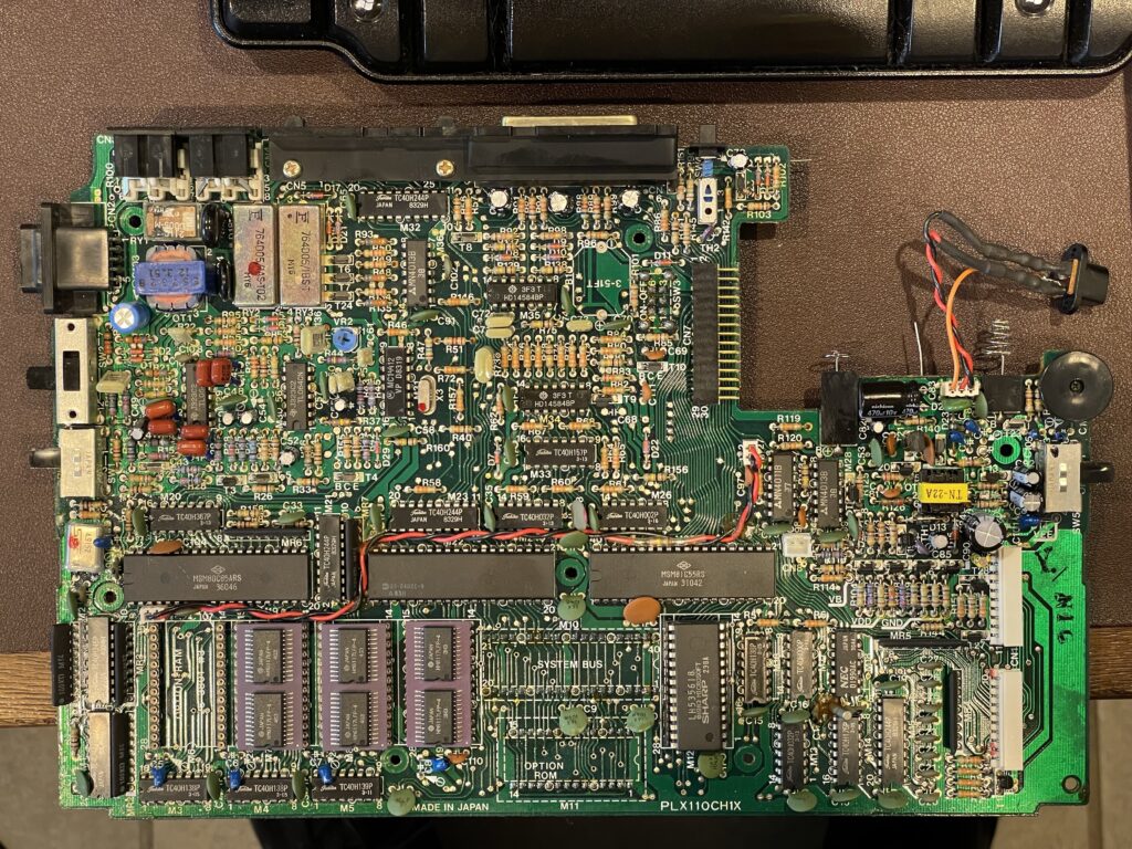
After replacing all of the electrolytic capacitors and verifying the correct polarity (where applicable) and the correct values, I powered up the Model 100 and saw the home menu – success! I felt around the board a bit for sources of heat and found no issues. None of the magic smoke was let out.
I tested the RS-232 port with my windows desktop using PuTTY and had no issues. As I experiment with various features of the Model 100 and its ports, I will be able to address any issues, if any arise.
Backpack Drive Plus
I purchased a Backpack Drive Plus (BDP+), which is a Tandy Portable Disk Drive emulator, among other things.
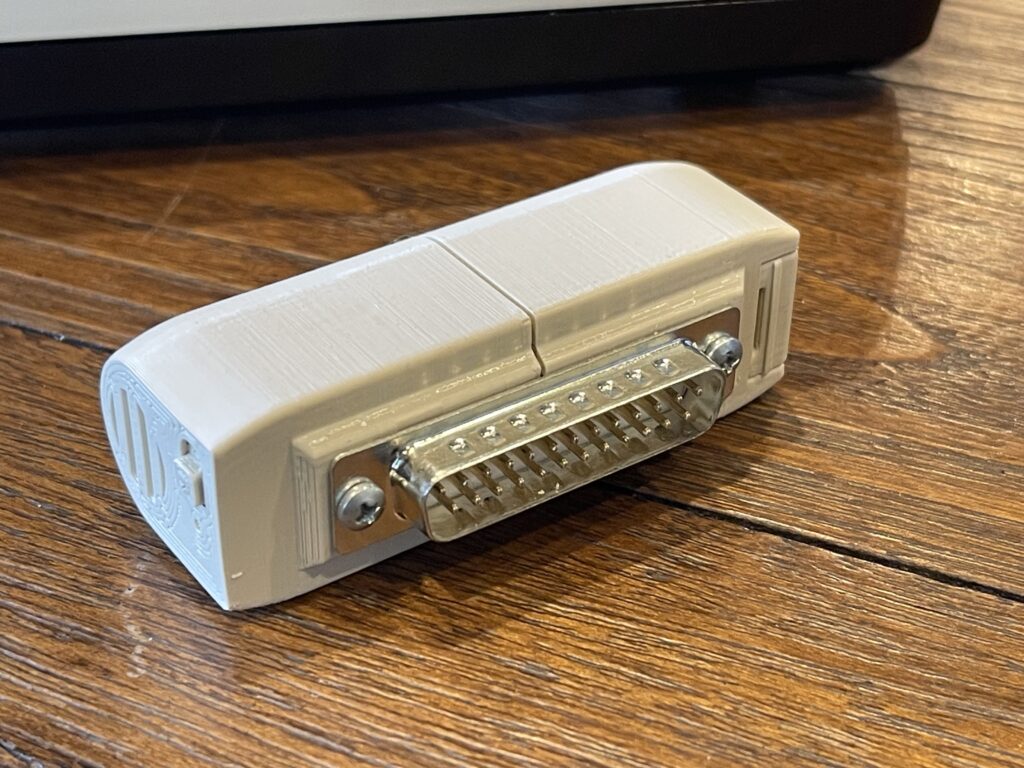
The BDP+ is a small device that attaches to an RS-232 port like the TPDD or TPDD2 would. It emulates the same command set which allows existing software to use it as-is, such as TS-DOS for example. It includes a bootstrap process built into the firmware to load TS-DOS, if you do not already have TS-DOS on a ROM or elsewhere.
Note that this loads TS-DOS into memory, which consumes a bit of RAM, and, might interfere with other assembly images you may wish to run (such as the bar code readers as an example). An alternative is to get TS-DOS on an option ROM and run it there.
The BDP+ uses a single “AA” battery and up to a 16 GB micro SD card for storage. It also includes a realtime clock and many other software features for a few other vintage computers in addition to the Model 100.
This will allow me to save (back up) my programs and data quite easily. The SD card can also be removed and read on a PC or Mac.
One thing to note with this device is if the battery is low, it will not return the directory of files and folders available when switching to the disk in TS-DOS. It will appear as if the drive is empty, leading you to believe you might have lost everything on the drive.
Since the BPD+ uses flash (SD Card), nothing is actually lost in this case, a battery change is all that is in order.
TS-DOS
TS-DOS is one of several utilities which support the TPDD protocol for working with files on disks. The documentation is attached below for reference.
LaddieCon
If you have a Windows PC, there is a TPDD emulator called LaddieCon. There is a version for Linux titled LaddieAlpha. Both run on a host PC which will emulate a TPDD, similar to a BPD+ device. This requires only a serial cable to connect your PC to the Model 100.
Once LaddieCon (or LaddieAlpha) is running, TS-DOS on the Model 100 will be able to list, download, or update files on the PC. This is a great option for backups and transferring files.
Bar Code Reader
The TRS-80 Model 100 had a bar code wand accessory, catalog number 26-1183. The wand plugs into the BCR (Bar Code Reader) port on the Model 100. It comes with a cassette tape for the programs and utilities to read various bar code formats.
The software included 3 bar code decoders:
- UPC-A
- 3 of 9
- Modified MSI Plessey
Each decoder is an assembly file, and can be used within a BASIC program as needed. First, the appropriate decoder (assembly program) must be loaded:
LOADM "UPC"After loading, the Model 100 will output the start address (top), end address, and entry point (exe):
TOP: 61788
END: 62611
EXE: 61824
The following sample program will read a UPC code:
10 CLEAR 100, 61788
20 RUNM "UPC"
30 OPEN "WAND:" FOR INPUT AS 1
40 INPUT #1, A$
50 PRINT A$
60 GOTO 40
At first, I could not get the bar code reader to work. The instructions mention to use the above sample program to get started. Upon execution of this sample program, I received an “FC Error” on line 10. I suspected the TS-DOS resident in RAM affected the values of MAXRAM, so I used the version of TS-DOS I have in ROM. This solved the “FC Error” on line 10. However, when testing the wand with a bar code, it still did not work.
I then tested the wand using a scope and DB9 breakout connector, and saw the serial data on the scope from the wand:
Knowing the wand was actually reading the differences between dark and light was a good place to start. Next, I used a test program from “Inside the TRS-80 Model 100” to see if the Model 100 can “see” the state changes from the wand:
1 IF 8 AND INP(187) THEN BEEP:GOTO 1 ELSE 1I did hear beeping as I dragged the wand across a bar code.
I then read the manual a few more times, and tried again, this time swiping across a bar code in the user manual very quickly. It worked!

The reader and decoder are quite particular and finicky. If I were to swipe across a bar code ten times, I am getting about a 50% read rate on average. Perhaps one of the things that the modern scanners do is control the scan rate with a vibrating plate and mirror. This eliminates the user training of speed and angle of the swiping. Modern scanners also do not need to be close to the bar code either. These bar code readers for the Model 100 (and similar ones) need to be in contact with the paper, and the tips can wear out.
I found the easiest way to get a reliable scan is to press and hold the scan button and swipe across the bar code fast, back and forth a bunch of times.
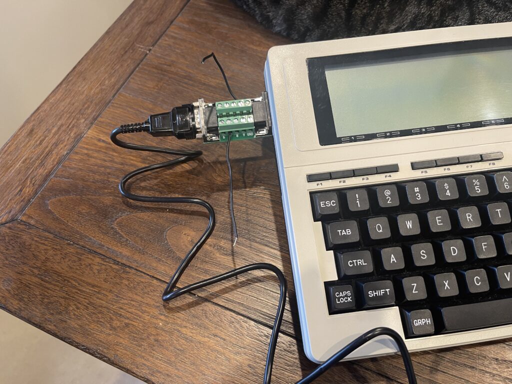
Terminal with an HF TNC
The Model 100 has a built-in terminal program which can be used to interface to a TNC for HF packet. I tried out the Model 100 with a KPC-3 and had some initial issues with garbled text on the screen above 300 baud. The TNC operates over RF at 1200 baud, and the baud rate on the terminal side can be set independently.
After some initial issues with higher baud rates, I eventually solved that problem. It was with the KPC-3 itself, not with the Model 100. I posted a separate article on that finding here.
Parallel Port
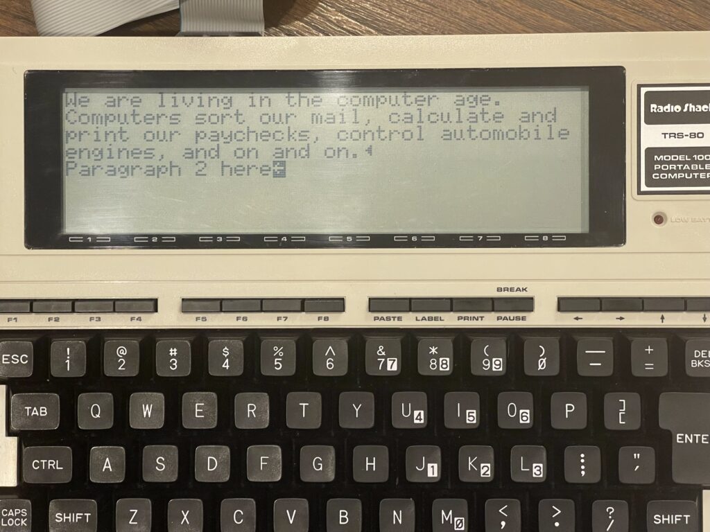
I connected an Epson TM-T88V thermal printer to the Model 100’s parallel port, opened the text editor on the Model 100, typed a sample paragraph and pressed PRINT (to print the entire document). Nothing happened. I then pressed SHIFT+PRINT (to print the screen), and the printer printed out my screen along with the previous buffer contents.
The TM-T88V printer has a large print buffer and will not flush it to paper until one of several specific conditions are met, such as a CR/LF combination is sent to it. The screen print on the Model 100 must satisfy that requirement whereas the full document print does not.
The challenge with printer compatibility with the Model 100’s built in print subroutines is finding a printer which does not need any control sequences, and prints everything in the buffer automatically (if it even has a buffer). Modern printers do not always meet this requirement.
It would appear there is also a mismatch between what the Model 100 sends after each line and what the printer expects. For example, some systems use a carriage return and line feed character to advance the paper to the next line and move the print head back to the left. These of course can be sent independent of each other, for bolding, underline, etc.
Other systems may not expect this combination and instead may only use line feed or carriage return but not both.
Of course, custom subroutines can be created, or BASIC programs to load and print a document quite easily. This buffer issue affects only the built in printing subroutines in the Model 100.
One thing to note is I enabled the automatic line feed on the printer via dip switch 1-1. This best simulates an old line printer with as little modification as possible needed when printing via BASIC.
For example, when using LLIST (list current program to printer) in BASIC, the printout was perfect. However, when using the TEXT application, only the screen print option worked as expected (SHIFT+PRINT).
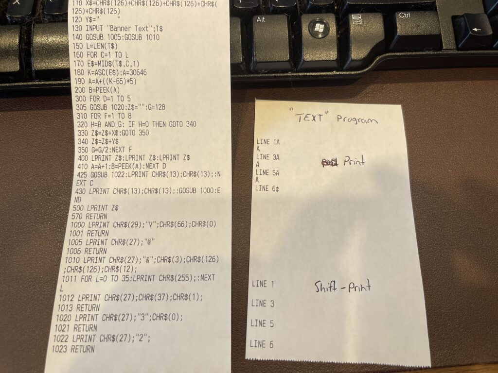
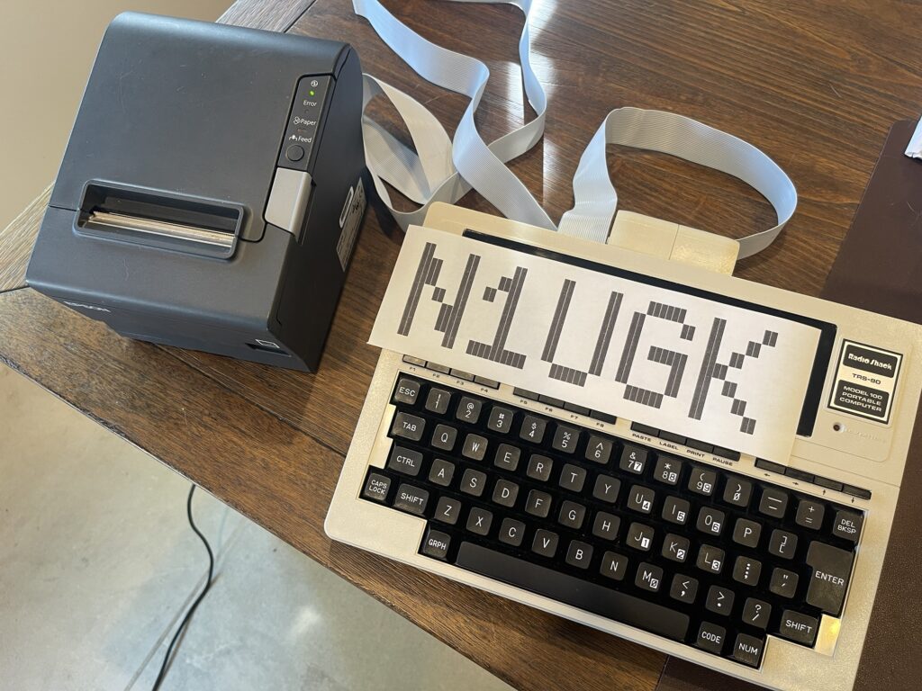
The print speed is incredible – the LLIST for the banner program took just over one second!
Banner Program
As with any computer I experiment with, I wrote a banner program for the Model 100. The banner program is a good way to become familiar with the BASIC capabilities of the particular vintage computer.
After successfully finding and connecting a vintage TP-10 thermal printer to the Model 100, I tried out a slightly modified version of my banner program for the PC-8. One of the items I wanted to improve for the Model 100 version was the character bitmap data.
When working with the PC-8, my original idea was to read the font bitmap data directly from the PC-8’s ROM using the undocumented PEEK command. However, the PEEK command on the PC-8 works only with the 2KB RAM memory space and not the ROM. I had to recreate the font bitmap myself and store it within a series of DATA statements in my program.
Even though the method I used for the banner program on the PC-8 was optimized for memory usage, it would have been far more optimized if I didn’t need to store the font bitmap as part of the program.
When working with the Model 100 version, my initial approach was to simply tweak only what was necessary to get the program to work with the TP-10 printer. However, further improvements could be made. The first and easiest improvement would be to use the Model 100’s built in font bitmap data instead of recreating it within the program using a series of DATA statements. This would not only save a bit of RAM, but it would also expand the character set supported by the program. This is because I would be able to use all of the characters the Model 100 has a bitmap for, as opposed to the limited characters I recreated by hand and included within the program itself.
The second enhancement to the program would be to modify it slightly to support the Epson TM-T88V thermal POS printer.
Finding the Characters
I had a few options for finding where in ROM the font bitmap data was hiding. First, I could search for a known pattern, such as the character “A”. Both the Model 100 and the PC-8 (along with most other pocket computers of the era) used the same or very similar 5 x 7 font. Therefore, if I knew how the letter “A” was stored in ROM, I could search for the pattern.
I suspected the storage of the font bitmap data in the Model 100 ROM would be the same approach I took with my PC-8 program. It would store the data as a series of 5 bytes per character, with each byte being a “row” of bits if the character were horizontally rotated.
To illustrate further, the letter “A” if rotated 90 degrees, is 7 pixels wide by 5 rows tall. This means I need 5 bytes of data to represent the character in a bitmap. In each of these bytes, each pixel in the row represents a bit in the same position within the byte. The 8th bit would usually be zero.
To illustrate further, the letter “A” if rotated 90 degrees, is 7 pixels wide by 5 rows tall. This means I need 5 bytes of data to represent the character in a bitmap. In each of these bytes, each pixel in the row represents a bit in the same position within the byte. The 8th bit would usually be zero.
BYTE 1: 01111100
BYTE 2: 00010010
BYTE 3: 00010001
BYTE 4: 00010010
BYTE 5: 01111100
For example, the first row, or byte 1 in the character “A” can be represented by a decimal value of 124 (111100 binary). The 8th bit would always be zero, since the font is only 7 pixels wide. In hexadecimal notation, this would be 0x7C. The next byte would be 0x12, and so on.
The letter A therefore can be represented by the following byte values: 0x7C, 0x12, 0x11, 0x12, 0x7C.
I could search the Model 100 ROM for these 5 bytes occurring in sequence. This would indicate where the letter “A” is stored, and then I can work from there to address the other characters. This could easily be done in BASIC if needed.
However, I figured it would be worth a try to search the world wide web for a ROM dump, ideally with some notes on where things are and what they do. Luckily, I ran across a ROM dump of the Model 100 on the club100.org site (from a member’s post). It had the following section:
; ======================================================
; LCD char generator shape table (20H-7FH
; ======================================================
7711H DB 00H,00H,00H,00H,00H,00H,00H,4FH
7719H DB 00H,00H,00H,07H,00H,07H,00H,14H
7721H DB 7FH,14H,7FH,14H,24H,2AH,7FH,2AH
7729H DB 12H,23H,13H,08H,64H,62H,3AH,45H
7731H DB 4AH,30H,28H,00H,04H,02H,01H,00H
7739H DB 00H,1CH,22H,41H,00H,00H,41H,22H
7741H DB 1CH,00H,22H,14H,7FH,14H,22H,08H
7749H DB 08H,3EH,08H,08H,00H,80H,60H,00H
7751H DB 00H,08H,08H,08H,08H,08H,00H,60H
7759H DB 60H,00H,00H,40H,20H,10H,08H,04H
7761H DB 3EH,51H,49H,45H,3EH,44H,42H,7FH
7769H DB 40H,40H,62H,51H,51H,49H,46H,22H
7771H DB 41H,49H,49H,36H,18H,14H,12H,7FH
7779H DB 10H,47H,45H,45H,29H,11H,3CH,4AH
7781H DB 49H,49H,30H,03H,01H,79H,05H,03H
7789H DB 36H,49H,49H,49H,36H,06H,49H,49H
7791H DB 29H,1EH,00H,00H,24H,00H,00H,00H
7799H DB 80H,64H,00H,00H,08H,1CH,36H,63H
77A1H DB 41H,14H,14H,14H,14H,14H,41H,63H
77A9H DB 36H,1CH,08H,02H,01H,51H,09H,06H
77B1H DB 32H,49H,79H,41H,3EH,7CH,12H,11H
77B9H DB 12H,7CH,41H,7FH,49H,49H,36H,1CH
77C1H DB 22H,41H,41H,22H,41H,7FH,41H,22H
77C9H DB 1CH,7FH,49H,49H,49H,41H,7FH,09H
77D1H DB 09H,09H,01H,3EH,41H,49H,49H,3AH
77D9H DB 7FH,08H,08H,08H,7FH,00H,41H,7FH
77E1H DB 41H,00H,30H,40H,41H,3FH,01H,7FH
77E9H DB 08H,14H,22H,41H,7FH,40H,40H,40H
77F1H DB 40H,7FH,02H,0CH,02H,7FH,7FH,06H
77F9H DB 08H,30H,7FH,3EH,41H,41H,41H,3EH
7801H DB 7FH,09H,09H,09H,06H,3EH,41H,51H
7809H DB 21H,5EH,7FH,09H,19H,29H,46H,26H
7811H DB 49H,49H,49H,32H,01H,01H,7FH,01H
7819H DB 01H,3FH,40H,40H,40H,3FH,0FH,30H
7821H DB 40H,30H,0FH,7FH,20H,18H,20H,7FH
7829H DB 63H,14H,08H,14H,63H,07H,08H,78H
7831H DB 08H,07H,61H,51H,49H,45H,43H,00H
7839H DB 7FH,41H,41H,00H,04H,08H,10H,20H
7841H DB 40H,00H,41H,41H,7FH,00H,04H,02H
We can see the letter A bitmap represented in the bitmap data above, highlighted.
What a convenient find! The banner program already works with the bitmap data in this format. Next, I needed to ensure that the characters are in a convenient or usable sequence. Ideally, in sequence that’s linear at least in part with the ASCII character set. This allows me to easily index this bitmap array.
As it turns out, all of the characters I tested for were in fact stored in a linear fashion with respect to the ASCII character codes.
Upon further testing and inspection, I found that some characters, such as the lower-case “g” and “j” used the 8th bit in the font bitmap data. Therefore, I modified the program to inspect and use the 8th bit.
Caveat
It is possible that other versions of the ROM for the Model 100 have the bitmap data in a different location than the version I have. Or, for other similar models, it might be in a different location, such as the Model 102 for example.
Improvements Made
Now that I know where the font bitmap data resides in the Model 100, I can modify the banner program further. I can remove the DATA bytes at the beginning of my program and reference the bitmap data in the ROM.
Further, every character on the keyboard is available to be used on the banners since this bitmap contains all of the characters, even lower case characters.
The banner program worked as expected and being able to use the font bitmap data in the ROM resulted in very little memory needed for the program.
The program listing for the banner program is below:
MODEL 100 BANNER VERSION 1.1
LCD 5x8 FONT IN ROM STARTS AT 0x7711
INIT AND LOOP THROUGH EACH CHAR IN STRING TO PRINT FOR BANNER
100 CLEAR : DEFINT B,G,L,K,D,F
110 INPUT “Banner Text”;T$
120 L = LEN(T$) : GOSUB 2500 : GOSUB 2000 : GOSUB 2100
130 FOR C = 1 TO L
READ TO LOCATION IN DATA ARRAY FOR CURRENT CHAR BITMAP
170 E$ = MID$(T$,C,1)
180 K = ASC(E$) : A = 30646
190 A = A + ((K - 65) * 5)
200 B = PEEK(A)
READ EACH ROW IN BITMAP FOR THIS CHAR
210 FOR D = 1 TO 5
215 FOR R = 1 TO 2
220 G = 128
230 FOR F = 1 TO 8
240 H = B AND G : IF H > 0 THEN LPRINT "~~~~~"; ELSE LPRINT " ";
250 G = G \ 2 : NEXT
260 GOSUB 3200 : NEXT
270 A = A + 1 : B = PEEK(A) : NEXT
275 GOSUB 2200 : GOSUB 3200 : GOSUB 3200 : GOSUB 2100 : NEXT
280 GOSUB 2200 : GOSUB 3200 : GOSUB 3200 : GOSUB 3200 : GOSUB 2300
290 GOSUB 2500 : END
REDEFINE "~" TO SOLID BLACK BOX, ENABLE CUSTOM FONT
2000 LPRINT CHR$(27);"&";CHR$(3);CHR$(126);CHR$(126);:CALL 27967,12
2010 FOR M = 0 TO 35 : LPRINT CHR$(255); : NEXT
2020 LPRINT CHR$(27);"%";CHR$(1);
2030 RETURN
SET LINE SPACING TO 0
2100 LPRINT CHR$(27);"3";CHR$(0); : RETURN
SET LINE SPACING TO DEFAULT
2200 LPRINT CHR$(27);"2"; : RETURN
CUT PAPER
2300 LPRINT CHR$(29);"VB";CHR$(0); : RETURN
RESET PRINTER
2500 LPRINT CHR$(27);CHR$(64) : RETURN
CRLF TO PRINTER
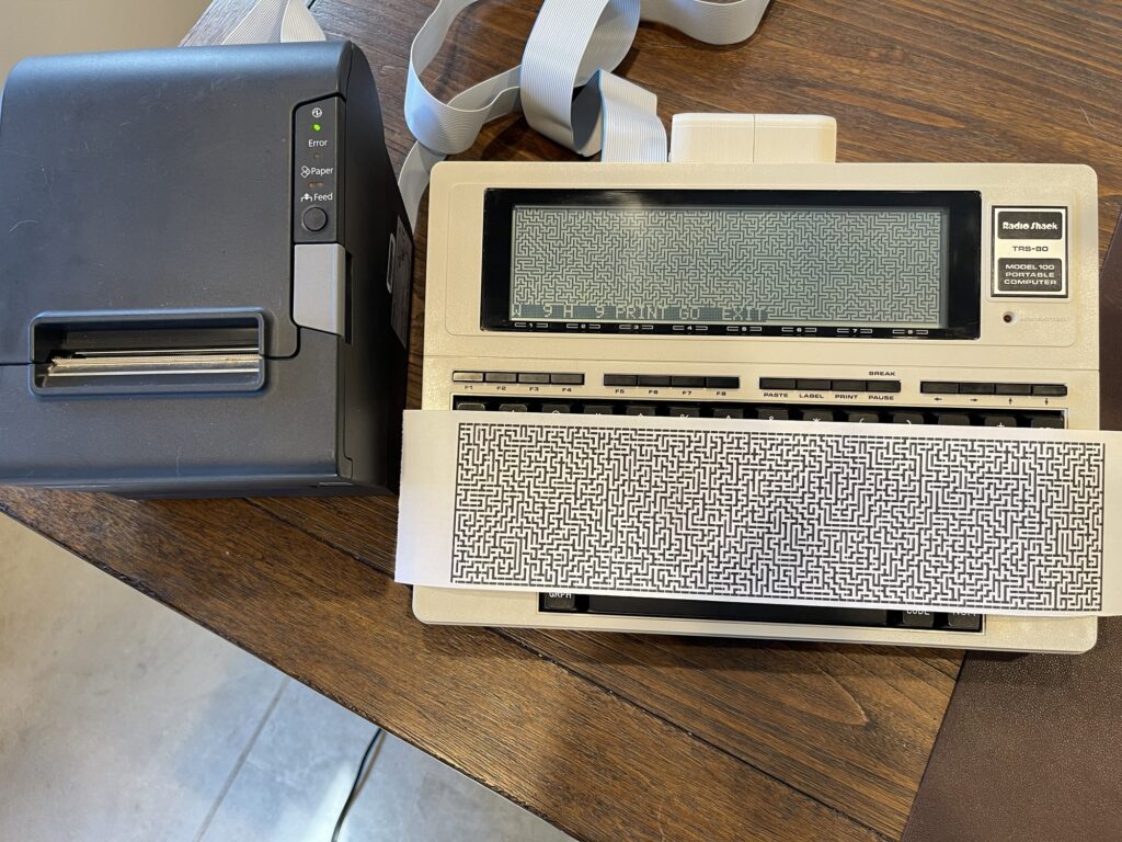
3200 CALL 27967,13 : CALL 27967,10 : RETURNMaze Program
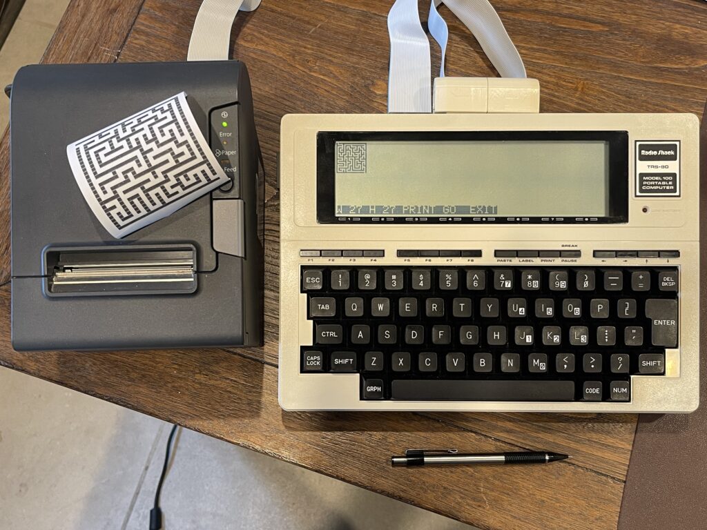
I have recently begun writing maze programs for various pocket computers as another way to become familiar with various platforms. Since the Model 100 has many printer options, I can generate a maze and then print it. The challenge however, is to have enough memory (RAM) in order to generate the maze using the algorithm chosen. The simplest algorithm to use for maze generation is the backtracking algorithm. It can easily be programmed in BASIC.
The algorithm requires the canvas size to be odd in both width and height, for example, 19 x 19, and not 20 x 20. The requirement for the canvas dimensions being odd instead of even is due to the interior lines or blocks needed for the maze. For example, lets consider a maze on a canvas size of 27 x 3:

The maze itself has a single pathway, given the height of the canvas is 3 pixels, and the pathway is in between the top and bottom walls. The next incremental height we can consider would be 5 pixels high, not 4 pixels. The same can be said for the width, for example flipping the maze dimensions to a 3 x 27 canvas. Therefore, the height and width of the canvas must always be an odd number.
A maze generator would need an actual canvas to work with (either on the screen, in memory, or both), and it would need a stack to push and pop in order to track where the algorithm has “walked” before. The algorithm will “push” to the stack as it walks uncharted territory on the canvas, and “pop” from the stack when it needs to back up (if it hits a wall or adjacent open space). The backtracking algorithm randomly chooses a direction with each step, with one of four possible directions (up, down, left or right). It will not be able to choose a direction that would hit a wall or an adjacent open space. Therefore, if no directions are possible for travel in the current position, it must “backtrack” until a direction is possible.
Once the algorithm reaches back to it’s start position, the maze is complete. The start position is randomly chosen, and must be an odd number for the x and y coordinate. The odd numbered coordinates are spaces marked open during traversal of the path, and the even numbered coordinates become the walls of the maze. Therefore, each step in the “walk” is really 2 pixels away from the current position (skipping over the even numbered coordinates), in any direction. When a walk is performed and a position is marked as open, the adjoining position (the even coordinate) between the previous location and current location is also marked as open.
Below is an example of the backtracking algorithm animated with JavaScript from professor-l Elle:
There are some prerequisites which are needed for a computer to generate a maze using the backtracking algorithm:
- A dot addressable display and/or a printer
- Enough RAM to hold the canvas and/or stack for the desired width and height of the maze
- Random number generator
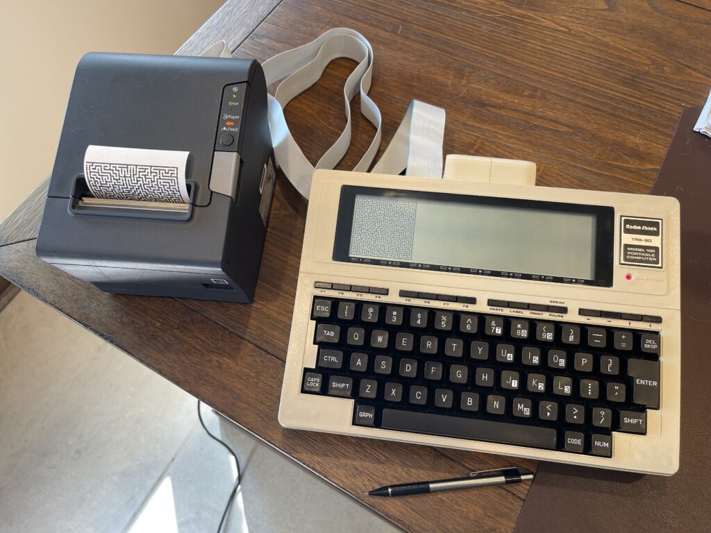
The Model 100 meets the prerequisites for a maze generator. Any line printer or thermal printer can be connected. Since I have an inexpensive Epson TM-T88V POS printer, I can connect it to the Model 100’s parallel port and print the mazes. Since Model 100’s have at least 8 KB of RAM, there should be plenty of memory for the stack.
Some computers with a dot addressable display have support to not only turning on or off a pixel at a time, but they also support reading the status of a pixel, eliminating the need to use additional user RAM for tracking pixel status. Although the Model 100 has BASIC commands for drawing lines (LINE) and setting pixels on and off (PSET, PRESET), it does not have a BASIC command to read the status of a pixel.
Memory Management
The larger the desired maze size, the more memory will be required to generate the maze. Since the Model 100 has a dot addressable display, the maze can be generated to the LCD display and then printed. The LCD has 240 pixels across and 64 pixels down for a total of 15,360 pixels.
Since the Model 100 has no BASIC method for reading the status of a pixel on the LCD, I need to either find a method to read a pixel state, or, track each pixel on my own in memory. Since there are 15,360 pixels, if a maze were to be drawn filling the entire display, then 15,360 bytes of memory would be needed (at most) to track each pixel. Even if I used a bit of memory per pixel rather than a byte per pixel, this would still require 1,920 bytes of memory and quite a bit of overhead to convert X,Y coordinates to bit locations in memory for tracking.
A maze generator could be used only for display on the screen, or it could also be used to print out the generated maze. The Epson TM-T88V can print 56 characters per line (for “Font B”). Due to the aspect ratio of this font, two horizontal characters are needed for each pixel for more of a square sized block when printing. This means that there are effectively only 28 “maze pixels” per line. Since the maze canvas size must be odd, this means the widest maze is 27 pixels. The height of course can extend as far as memory and paper length would allow for.
Many pocket computers have PEEK and POKE commands in BASIC which allow for memory space to be consumed directly, byte by byte. Computers which do not have these commands are limited to the built-in variable management supported by the model. Luckily, the Model 100 not only supports PEEK and POKE, but it supports up to three levels of variable sizes for numerics: integer, single-precision, and double-precision. Each requires 2, 4, and 8 bytes respectively. If I use integer variables, I can avoid manual memory management using PEEK and POKE.
To declare an array of integer (2-byte) values, the format would be:
DIM X%(24)The array of 25 integer variables would consume 50 bytes of user RAM.
In addition to possibly needing memory for the canvas, I definitely need memory for the stack. The stack holds previously open spots when walking the canvas, using the backtracking algorithm. Since I need to track X and Y coordinates for the path, I need two positions in the stack for each coordinate. The total number of entries needed for the stack varies depending on the longest possible “path”.
The worst case scenario would be a path which starts in a corner and winds along the outside walls until reaching the center. This of course is nearly impossible given the randomness of the direction chosen. Therefore, the stack size is chosen as an average maximum. I chose a stack size of 1/2 the height and width of the canvas, and a single stack for the X coordinates and Y coordinates.
DIM X%(W * H \ 2)Since the smallest variable size is 2 bytes (integers), I can use a single location to store both X and Y coordinates. Integer values can be no more than 32,767 on the Model 100 (or no less than -32,768). Since the largest X coordinate value would be 239 and the largest Y coordinate would be 63, I can store both in the same integer location by shifting the Y coordinate over by 8 bits and add it to the X coordinate.
This method can be illustrated using the maximum value of the X and Y coordinates 239 and 63:
DIM X%(1)

X = 239
Y = 63

X(0) = X + Y * 256
Both the X and Y coordinate value is stored at X(0). To recover X and Y, the reverse can be done:
X = X(0) AND 255;
Y = X(0) \ 256;
Note that the “\” operator is integer division.
Using the logic above, for a 27 x 27 canvas size, the stack would require another 729 bytes total (27 x 27 / 2 * 2). Since the dimensions of the canvas will not exceed three digits, an X and Y coordinate can be appended together by shifting the Y coordinate by 8 bits and adding it to the X coordinate.
For a full screen canvas size of 239 x 63, 15,057 bytes of memory would be needed for the stack, at most.
Tracking LCD Pixel State
Since there is not a BASIC command to detect pixel state, and to use as little RAM as reasonable for the maze generator, I found a clever method for reading pixel state. This avoids having to track pixel state in a separate block of memory, greatly reducing memory usage.
On the Club 100 site, I ran across an LCD tips document which had a method to read pixel state. I have included the document below as a reference:
The clever trick is to move the cursor over to the area on the LCD screen where we want to read the current pixel state for using the PRINT command in BASIC. Then, use an invert subroutine in ROM to invert those pixels in the 6 bit area of the pixel we want to read the state for. The same subroutine can then be called again, which would invert those bits back to their original state, leaving a copy of that state in a byte of RAM. We can then read the associated bit and detect its state.
The example subroutine is:
1100 PRINT@40*(PY\8)+PX\6,;
1110 CALL 17786
1120 CALL 17786
1130 FL=PEEK(PXMOD6-20)AND2^(PYMOD8)
1140 IF FL THEN BEEP
1150 RETURN
In the example above, the input would be PX and PY, the X and Y coordinates of the pixel to read the status of. The first line moves the cursor to the character position given the X and Y input and then does not actually print anything.
The CALL to 17786 is the subroutine in ROM for inverting the current column. The PEEK in line 1130 reads the appropriate byte in the character position and the appropriate bit within that byte. If FL is positive, then the pixel is on.
Now that I had a good method for detecting pixel state, I could move on to the next challenge for the maze generator for the Model 100.
Random Number Generation
The Model 100 supports random number generation using the RND function. If passing a 1, the next value in the sequence will be returned. If passing in a zero, the last value will be returned. If a negative number is passed, it will seed the generator with that number.
However, the Model 100 does not have a built-in seed generator. The same random numbers will be returned each time you run a BASIC program.
A method for random seeding could be to grab the seconds value from the real-time clock and jump to that position in the random number sequence:
95 R = VAL(RIGHT$(TIME$, 2))
96 FOR I = 1 TO R
97 DUMMY = RND(1)
98 NEXT
However, this is not perfect, as it would give only 60 different sequences.
I read on a Model 100 email list about an area in memory which is written to with values ranging from 1 to 125 frequently. Reading this value and writing it to the seed value for the randomizer also works and might be a bit faster:
POKE 64634, PEEK(63791)For the purposes of this maze generator, this will work well enough.
Rounding Function
The Model 100 does not support a rounding function built-in. Since most random number generators return a decimal or double from zero to one, I needed a function to convert this random number into an integer. Normally we simply multiply the random number generated by a number representing the desired upper limit. For example, in this case, I needed a random number from zero to three for indexing an array:
R = RND(1)*3;In the example above, the random number “R” will be in the range between 0 and 3 as a double (or decimal). If you cast a double to an integer, you get just the whole number portion of the value. For example, 2.86 cast to an integer is 2. Of course, we likely want 3, and a rounding function would do this.
The simple solution to this would be:
R = INT(RND(1)*3 + 0.5)In the example above, integer “R” is assigned a value using a cast, but before the cast we add 0.5. This allows for the “rounding up” logic we expect from a rounding function.
Limited Support with LPRINT
When using a printer which supports ESC/POS, such as the Epson TM-T88V, some escape sequences had byte values not supported by LPRINT. For example, I would send a character to the printer such as byte value 0, using the following:
LPRINT CHR$(0);While the value zero worked, a value of 9 did not work. It appears the LPRINT command filters out or bypasses some values which are not considered displayable or printable. Other examples include carriage return (13) and line feed (10).
I found a subroutine in ROM that will send any value to the printer port. For example, to send a CR and LF to the printer:
CALL 27967,13 : CALL 27967,10This solved the issue I was having with some of the escape sequences needed to set a custom character into the Epson TM-T88V.
Maze Program Listing
After much trial and error and working around limitations in BASIC for the Model 100, I was able to create a maze program using as little memory as reasonable.
The listing for the maze generator is below:
TRS-80 MODEL 100 MAZE GENERATOR VERSION 1.6

5 CLS
10 CLEAR : DEFINT B,W,H,X,N : KEY 1,"W" : KEY 2,"H" : KEY 3,"P" : KEY 4,"G" : KEY 5,"X" : W = 27 : H = 27 : DIM N%(3,1) : PW = 28 : DIM X%(7680) : GOTO 9100
20 B = 0 : CLS
30 W = W - (W MOD 2) + 1
40 H = H - (H MOD 2) + 1

FILL WORKSPACE WITH CLOSED BLOCKS

50 LINE(0,0) - (W-1,H-1), 1, BF

CUT OPENING AT TOP

80 PRESET(1,0)

RANDOM START SOMEWHERE

95 POKE 64634, PEEK(63791)
100 CY = INT(RND(1) * (H-2)+0.5) + 1
110 IF CY MOD 2 = 0 THEN 100
120 CX = INT(RND(1) * (W-2)+0.5) + 1
130 IF CX MOD 2 = 0 THEN 120
140 PRESET(CX,CY)
150 X(B) = CX + CY * 256 : B = B + 1
160 GOTO 210

POP NEXT OPEN SPACE OFF STACK

200 IF B = 0 THEN 580
205 B = B - 1 : CX = X(B) AND 255 : CY = X(B) \ 256

GET ADJACENT SPACES NOT OPEN YET

210 GOSUB 1000

IF NONE FOUND, POP PREVIOUS OPEN SPACE OFF STACK

500 IF NC = 0 THEN 200

RANDOM CHOICE MADE, OPEN AND JOIN TO PREVIOUS

530 CH = INT(RND(1)*(NC-1) + 0.5)
540 X(B) = N(CH,0) + N(CH,1) * 256 : B = B + 1
550 PRESET((N(CH,0)+CX)/2, (N(CH,1)+CY)/2)
560 PRESET(N(CH,0), N(CH,1))
570 CX = N(CH,0) : CY = N(CH,1) : GOTO 210

CUT OPENING AT BOTTOM, BEEP AND PAUSE, THEN PRINT

580 PRESET(W-2,H-1) : PRESET(W-2,H-2)
590 BEEP : GOSUB 3500
600 GOTO 9100

FIND ADJACENT OPEN BLOCKS

1000 NC = 0 : YP = CY + 2 : YM = CY - 2 : XP = CX + 2 : XM = CX - 2
1010 PX = CX : IF YM > 0 THEN PY = YM : GOSUB 1100
1020 IF YP <= H THEN PY = YP : GOSUB 1100
1030 PY = CY : IF XM > 0 THEN PX = XM : GOSUB 1100
1040 IF XP <= W THEN PX = XP : GOSUB 1100
1050 RETURN

READ PIXEL STATE

1100 PRINT@40*(PY\8)+PX\6,; : CALL 17786 : CALL 17786
1130 FL=PEEK(PX MOD 6 - 20) AND 2^(PY MOD 8)
1140 IF FL THEN N(NC,0) = PX : N(NC,1) = PY : NC = NC + 1
1150 RETURN

REDEFINE "~" TO SOLID BLACK BOX, ENABLE CUSTOM FONT

2000 LPRINT CHR$(27);"&";CHR$(3);CHR$(126);CHR$(126); : CALL 27967,9
2010 FOR M = 0 TO 25 : LPRINT CHR$(255); : NEXT : LPRINT CHR$(255);
2020 LPRINT CHR$(27);"%";CHR$(1);
2030 RETURN

SET LINE SPACING TO 0

2100 LPRINT CHR$(27);"3";CHR$(0); : RETURN

SET LINE SPACING TO DEFAULT

2200 LPRINT CHR$(27);"2"; : RETURN

CUT PAPER

2300 LPRINT CHR$(29);"VB";CHR$(0); : RETURN

SET FONT "B"

2400 LPRINT CHR$(27);"M1"; : RETURN

RESET PRINTER

2500 LPRINT CHR$(27);CHR$(64) : RETURN

PRINT MAZE USING CUSTOM CHAR

3000 GOSUB 2500 : GOSUB 2100 : GOSUB 2400 : GOSUB 2000
3005 FOR PX = 0 TO W - 1 : LPRINT "  ";
3010 FOR PY = 0 TO H - 1
3020 PRINT@40*(PY\8)+PX\6,; : CALL 17786 : CALL 17786
3050 FL = PEEK(PX MOD 6 - 20) AND 2^(PY MOD 8)
3060 IF FL THEN LPRINT "~~"; ELSE LPRINT "  ";
3070 NEXT
3080 IF H < PW THEN GOSUB 3200
3090 NEXT
3100 GOSUB 2200 : GOSUB 3200 : GOSUB 3200 : GOSUB 3200
3110 GOSUB 2500 : GOSUB 2300
3120 RETURN

CRLF TO PRINTER

3200 CALL 27967,13 : CALL 27967,10 : RETURN

PRINT MAZE AT 180 DPI

3300 GOSUB 2500 : GOSUB 2100 : NH = H * 8 \ 256 : NL = (H * 8) AND 255
3305 FOR PX = 0 TO W - 1 : LPRINT CHR$(27);"*"; : CALL 27967,33 : CALL 27967,NL : CALL 27967,NH
3310 FOR PY = 0 TO H - 1
3320 PRINT@40*(PY\8)+PX\6,; : CALL 17786 : CALL 17786 : FL = PEEK(PX MOD 6 - 20) AND 2^(PY MOD 8)
3332 IF FL THEN FL = 255 ELSE FL = 0
3333 PX = PX + 1 : PRINT@40*(PY\8)+PX\6,; : CALL 17786 : CALL 17786 : FM = PEEK(PX MOD 6 - 20) AND 2^(PY MOD 8)
3334 IF FM THEN FM = 255 ELSE FM = 0
3335 PX = PX + 1 : PRINT@40*(PY\8)+PX\6,; : CALL 17786 : CALL 17786 : FN = PEEK(PX MOD 6 - 20) AND 2^(PY MOD 8)
3336 IF FN THEN FN = 255 ELSE FN = 0
3337 FOR G = 0 TO 7 : CALL 27967,FL : CALL 27967,FM : CALL 27967,FN : NEXT
3370 PX = PX - 2 : NEXT : GOSUB 3200
3390 PX = PX + 2 : NEXT
3400 GOSUB 2200 : GOSUB 3200 : GOSUB 3200 : GOSUB 3200 : GOSUB 3200
3410 GOSUB 2500 : GOSUB 2300
3420 RETURN

DETERMINE PRINT DENSITY

3500 IF H <= 27 THEN GOSUB 3000 : RETURN
3510 IF H <= 63 THEN GOSUB 3300
3520 RETURN

VALIDATION
4000 IF H > 63 THEN H = 63
4005 IF H < 3 THEN H = 3
4010 IF W > 240 THEN W = 240
4015 IF W < 3 THEN W = 3
4020 RETURN

MENU

9000 CALL 17001 : PRINT@280,; : PRINT USING "W### ";W; : PRINT USING "H### ";H; : PRINT "PRINT GO  EXIT";
9010 CALL 17006
9020 RETURN

9100 BEEP : GOSUB 9000
9110 K$=INKEY$
9120 IF K$="G" THEN 20
9130 IF K$="W" THEN CLS : INPUT "Width";W : GOSUB 4000 : GOSUB 9000
9140 IF K$="H" THEN CLS : INPUT "Height";H : GOSUB 4000 : GOSUB 9000
9150 IF K$="X" THEN 9200
9160 IF K$="P" THEN GOSUB 3500
9170 GOTO 9110

EXIT AND RESET MENU KEYS

9200 CALL 23164, 0, 23366 : CALL 27795
9210 END
Variable PW is the printer width in “canvas pixels”, in this case 28 maximum for this printer using “Font B”. For greater printer widths, this can be adjusted. W and H are the width and height for the canvas. The minimum is 3 x 3 and maximum for the LCD display is 239 x 63. With the Epson TM-T88V, it can print the maximum LCD canvas size using bitmap graphics mode.
In order to support a larger printout, since the width is fixed at a maximum of 27 for character mode and 63 for bitmap mode, the length can be as high as 239. When printing, I have the algorithm rotating the maze by 90 degrees, flipping the width and height. This allows for the maximum canvas printout of 239 x 63.
An improvement for this version of the maze generator over the previous versions is the option to print in a higher density if the width is greater than 27. For higher density printing, I use the graphics mode of the Epson TM-T88V with double density 24 dot mode, which is equivalent to 180 dpi horizontal and vertical (1:1 aspect ratio). I am using 8 x 8 dot blocks when printing, and 3 canvas rows per line sent to the printer in bitmap mode.
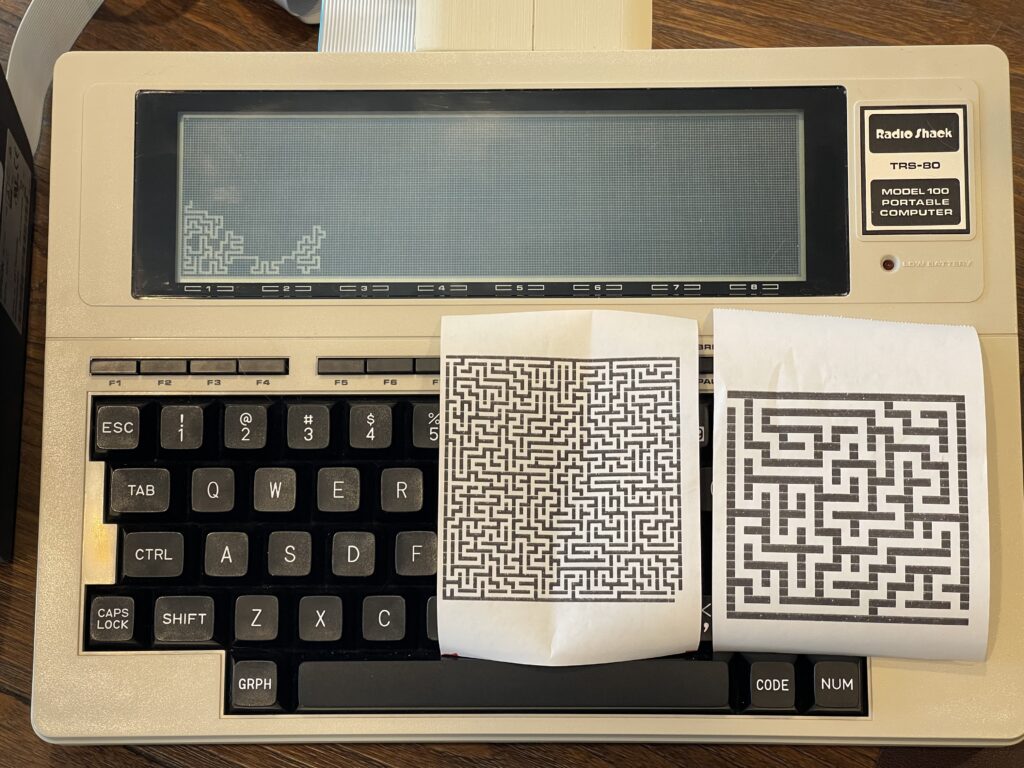
The largest canvas size is 239 x 63, which takes just over 36 minutes to render on the Model 100. With the option to print in increased density, this allows me to render a full screen maze and print it on the Epson TM-T88V.

Other Software
Awhile back I had purchased a ROM module which has 8 ROMs in one flash chip. This ROM has a series of dip switches (three) which are used to select the desired ROM. 4 of the ROMs are for the Tandy 200, while the other 4 are for the Model 100/102.
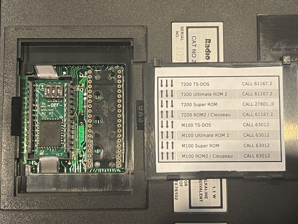
For the Model 100/102, the 4 ROMs included in the flash chip are TS-DOS, Ultimate ROM 2, Super ROM, and ROM2 / Cleuseau.
For the time being, I have used only the TS-DOS ROM. Each of these ROMs has an associated user guide and an initialization step, which is simply a CALL to a hook in the ROM to add the entry point to the main menu.
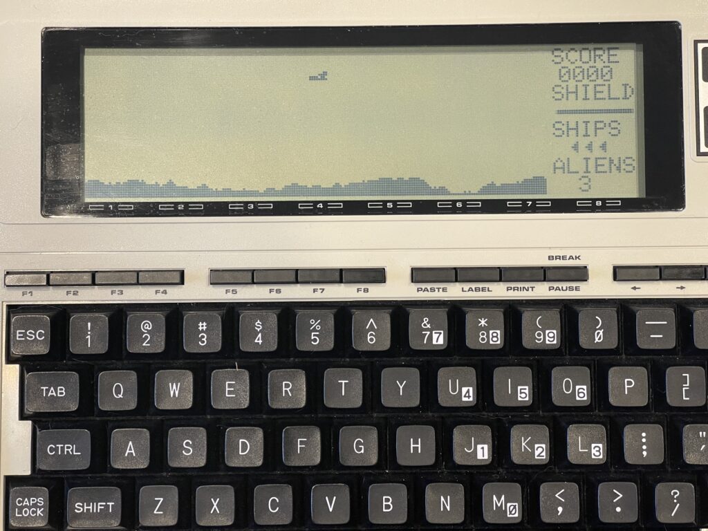
Games
Starblaze-100 was sold by Radio Shack and distributed on cassette. The program is an assembly language program (not BASIC). This game can be loaded via LaddieCon or a backpack drive.
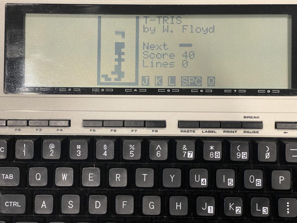
I found a Tetris clone on the Club 100 site, also written in assembly which runs very well:
Final Thoughts
Now that I have replaced the electrolytic capacitors and replaced the leaky NiCd backup battery in my Model 100, I am going to experiment more with BASIC and 8085 assembly.
In creating the banner program, maze generator, and using the terminal with a TNC, I have become familiar enough with the Model 100 to really appreciate its capabilities, and see first hand how innovative this was for 1983 technology.
I plan to use the Model 100 with HF & VHF TNCs for Amateur Radio and with the FT5D HT for APRS.
There is a group of Model 100 enthusiasts here, and an organization with files, documentation and more here.
Josh Malone had given a presentation on repairing Model 100’s at Tandy Assembly 2019 and the video can be viewed here.
This whole document is so great. I just came across this today. have you made any more progress with your M100?
Hi Scott, the article has been updated quite a few times, most recently with the maze program as an exercise in BASIC on this model, with the “backpack drive”, LaddieCon, the bar code reader wand, and the cassette interface with the matching recorder. I’ve been working on updates over time on the M100, and my next project is to clean up all of the factory flux off the board before it causes any problems.