
Kantronics KAM All Mode TNC for HF Packet Radio
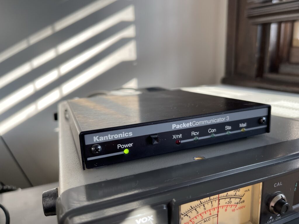
Recently, a few local amateur operators and I were testing packet on 2-meters. I set up my Kantronics KPC-3 on a known packet frequency on the FT-991A and enabled the PBBS built into the KPC-3 and left it running over a weekend. I set the TNC to beacon to every 10 minutes.
After a weekend I was amazed to see how many nodes were out there within reach and active. I had a few messages awaiting on the TNC by Monday morning.
Kantronics, among a few other TNC manufacturers, created a local message store in the firmware which allows for users to connect to the node and read or write messages for either the node owner or other users. These are often referred to as Personal Bulletin Board Systems or PBBS for short.
Of course these PBBS features implemented in 80s and 90s era TNCs had some limitations such as the number of messages they can store and the number of simultaneous connections they can support. But, they did offer a simple way to leave a node on the air 24/7 without the need for a PC to handle the PBBS tasks.
It had been decades since I have used the PBBS in this TNC and it reminded me of the days when I would come back from a long day at college to find a message waiting for me on the TNC (message LED blinking on the front panel). It also reminds me of answering machines, but that’s a different story.
The other station I was testing with, KD2YCK, was trying out some software based solutions for AX.25, the modem, and the terminal emulation. He was able to successfully configure a software solution that fully emulated a hardware TNC. He was able to connect to my node, read and drop a message and disconnect.
He then challenged me to the same, but on HF. There were quite a few stations with PBBS nodes on HF and in conversation mode on 20-meters. His software configuration supported HF mode as well.
I enjoy a good challenge and set out to get on HF packet.
Differences Between VHF and HF
Since I had the hardware TNC already, I attempted HF packet with the Kantronics KPC-3. Without really reading much about the topic, I tuned to 14.105 LSB and listened. It sounded a bit like the old fax machines, not quite like packet on VHF. Of course the baud rate below 30 MHz must not exceed 300 baud, but the tones were different in pitch also.
I then began to read up on the topic and discovered the HF tones and spacing are different on HF than they are on VHF on up. Further, my model of TNC does not have an option to change the tone nor the spacing. It only allowed for the change of RF baud rate, including 300 baud.
Kantronics KAM All Mode Communicator
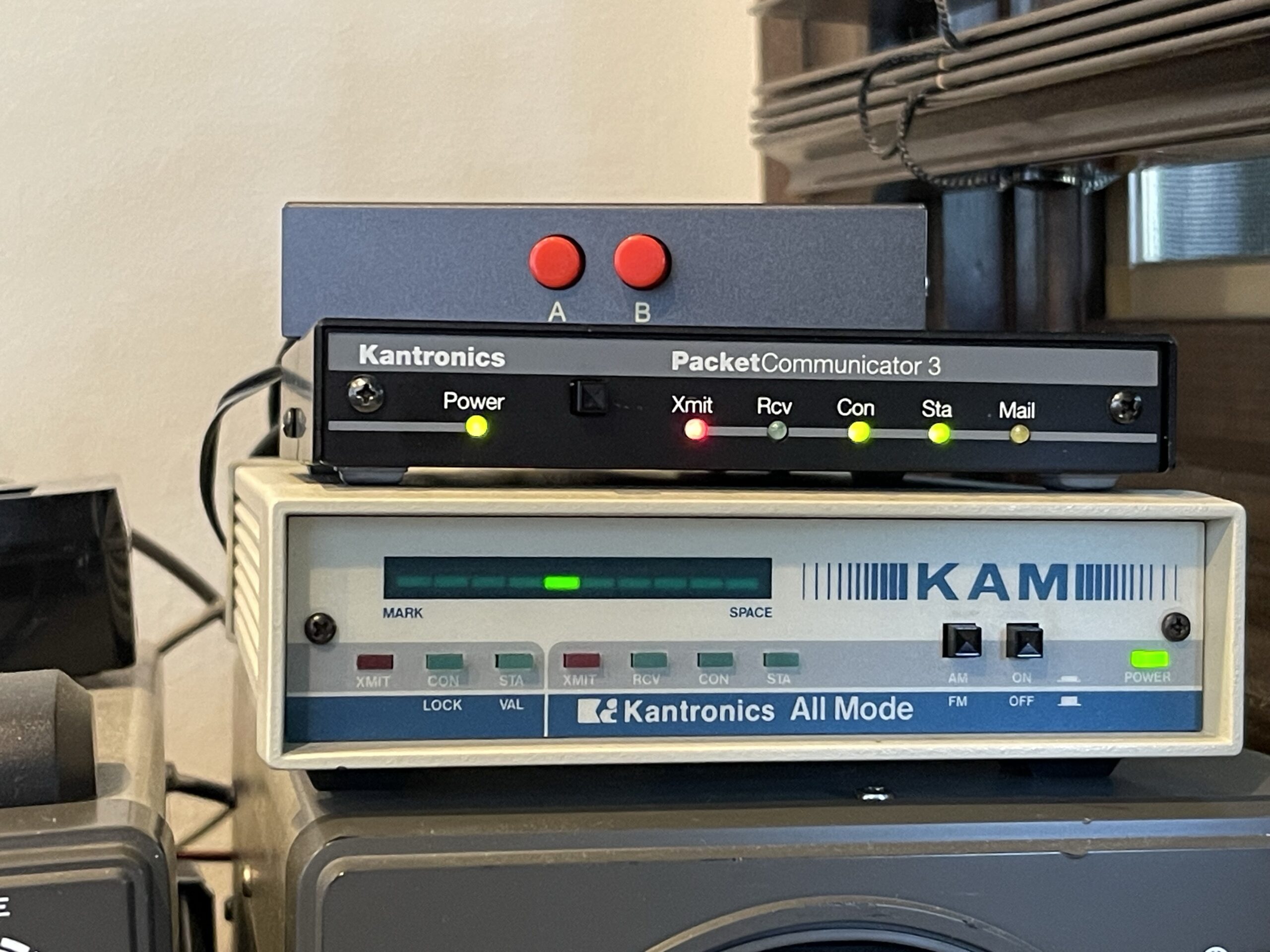
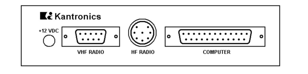
Since I’m a fan of vintage hardware, I set out to find a deal on a TNC that could work on HF. I found a Kantronics KAM All Mode TNC for a decent price on eBay. This TNC has 2 TNCs in one, or two ports, one for VHF and another for HF:
HF Packet Mode: This unit incorporates the necessary circuits and firmware to provide Packet operation on the High Frequency bands. When Packet operation is selected, a tone pair of 1600/1800 Hertz and an output Baud rate of 300 is established. You may designate other tone pairs if you prefer, however, you should remember to generally maintain a 200 Hertz shift. Other shifts can be established, but doing so could make a difficult for other packet stations to copy your signals unless they are also using the same shift.
VHF Packet Mode: Packet operation is available using standard Bell 202 tones of 1200/2200 Hertz only at 1200 Baud
Further, I suspect there are some differences in the TNC for decoding which work better for HF. Since VHF packets are received in FM mode, decoding is done without having to deal with fading and phase issues that could be present on HF in SSB mode.
This particular TNC also has a PBBS and can even work as a gateway between the HF and VHF ports.
Connections to the FT-991A
Because I am using a single rig for both HF and VHF, the FT-991A, it has only a single port for data communications in the back.
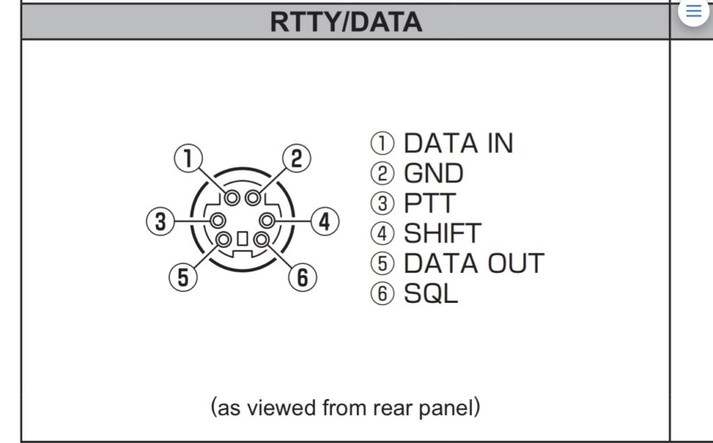
The data port on the FT-991A is a PS/2 style port which is still easy to find connectors for. Awhile back I found a PS/2 male to male cable on Amazon and used one half of the cord and a DB9 connector for connecting the FT-991A to my KPC-3.
I could easily connect the KAM all mode TNC to the FT-991A (the VHF side of the TNC) using the same cable I made for the KPC-3. However, I also want to connect the HF side of the all mode TNC to the FT-991A.
Since the FT-991A has HF and VHF, I need a way to connect both ports on the KAM to the FT-991A. In order to avoid plugging in and unplugging the two ports from the TNC to the FT-991A when switching between VHF and HF packet modes, I chose a simple solution.
Back in the late 90s when I was using the KPC-3, I had used it with both an HT and a Yaesu FT-2500M. The FT-2500M does not have a data port, but it can be used with TNCs via its 8 pin RJ45 microphone connection. This is possible due to the FT-2500M having an audio output from the rig available on one of these pins on the RJ45 connection. This is not the case on the FT-991A. If you wanted to use the microphone connection on the FT-991A with a TNC, you would need to find a source for the audio out from the rig to the TNC, such as the headphone or external speaker connection.
TNC A/B Switch
The solution I chose was to use an A/B switch. Since I didn’t find an A/B PS/2 switch, I found an economical (cheap) way to switch the single data port on the FT-991A between two TNCs. I found an RJ45 A/B switch.

With this switch, I can switch between the HF and VHF ports on the KAM All Mode TNC to the single data port on the FT-991A. Or, I can switch between the KPC-3 for VHF and the KAM for HF. This avoids swapping PS/2 plugs in the back of the FT-991A.
This switch has 3 RJ45 connections in the back. One connection is for the common or output. The other two connections are for device A and B.
I built a PS/2 to RJ45 cable to connect the common or output on the A/B switch to the FT-991A data port. I then built two more RJ45 to TNC cables. One was for the DB9 VHF port and the other for the DIN HF port.
Testing
Before testing the KAM, the new variable in my setup was the A/B switch. Because my KPC-3 was previously connected directly to the FT-991A and working, I connected this TNC to the A/B switch first and see if it worked. I confirmed the KPC-3 TNC was able to connect on a Winlink connection. This proved the A/B switch idea worked.
Before connecting the KAM to the FT-991A via the A/B switch, I wanted to verify the serial connection so that I can configure and check the status and settings on the KAM.
Similar to the KPC-3 and other newer Kantronics TNCs, the KAM can be set to auto baud rate on power up. When powering on, you wait on the terminal for a legible notice to press “*” on the keyboard. The TNC then locks on the current baud rate. Using the ABAUD command, you can set a preferred baud rate on startup.
For my first test of the setup, I was unable to see this message. I saw nothing but garbled text. I checked the TTL/RS-232 level jumper on the PCB and it had been set for TTL.
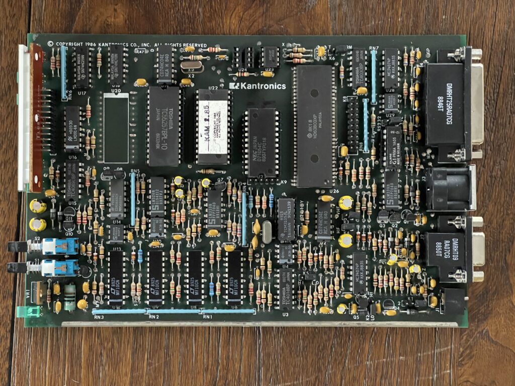
As with almost all vintage electronics with jumpers and firmware, I recommend taking a picture of the PCB so that you can simply view the picture if you question jumper positions or firmware versions. This is certainly easier than removing the PCB from the case each time you have a doubt about a jumper setting for example.
After setting the serial level jumper from TTL to RS-232, I saw the startup message from the TNC! Next, I connected the KAM to the A/B switch in order to connect it to the FT-991A. I tuned to 14.105 LSB on the FT-991A and parked there for awhile waiting for some packet activity.
FT-991A Data LSB/USB Mode Issue
I used the Data LSB mode (or Data USB mode) on the FT-991A when using the HF side of the TNC. This instructs the rig to use the data port for incoming audio. The alternative would be to use the regular LSB mode, and then changing menu 106 SSB MIC SELECT from MIC to REAR. This is less than ideal, because it would require a change in the menu each time I wanted to switch between packet and voice.
However, if using the FT-991A for digital modes with a computer via the USB sound card, then menu item 72 needs to be changed from USB back to Rear, the default. Then, when using the digital computer mode(s), this menu item needs to be changed back to USB.
When switching to Data USB or Data LSB on the FT-991A, the bandwidth was reduced. It sounded as if a CW filter had been turned on. I checked to ensure the mode was “wide” and width was up to 3000. However these settings in the function menu made no difference.
The problem was a setting in the setup menu. The defaults in menu item 065 OTHER SHIFT set at the default of 0. Once I changed this to the mid point between 0 and 3000 (1500) the narrow audio was opened to the same width the regular SSB modes had. I have to credit KD2YCK for the help in solving that issue.
After quite a bit of testing and experimenting, I found that a width setting of 800Hz on the FT-991A worked well to filter out adjacent signal and noise sources while still being able to “hear” the 1600/1800Hz tones for the TNC to decode.
Dual Port TNCs
I then began the task of familiarizing myself with this TNCs commands and options. I’m familiar with the Kantronics command set generally, but this TNC is a bit more involved because it has two ports. For example, when issuing a connect command, what port would the TNC connect using, the HF or VHF port?
This TNC directs its commands to ports via the selected “stream”. This TNC has 16 streams by default (can be changed using the MAXUsers command), the first 8 are HF and the second 8 are VHF.
You can switch streams by issuing the stream switch character followed by the stream number. For example, to determine the stream switch characters, type STR. The TNC will respond with the hexadecimal ASCII characters for HF/VHF.
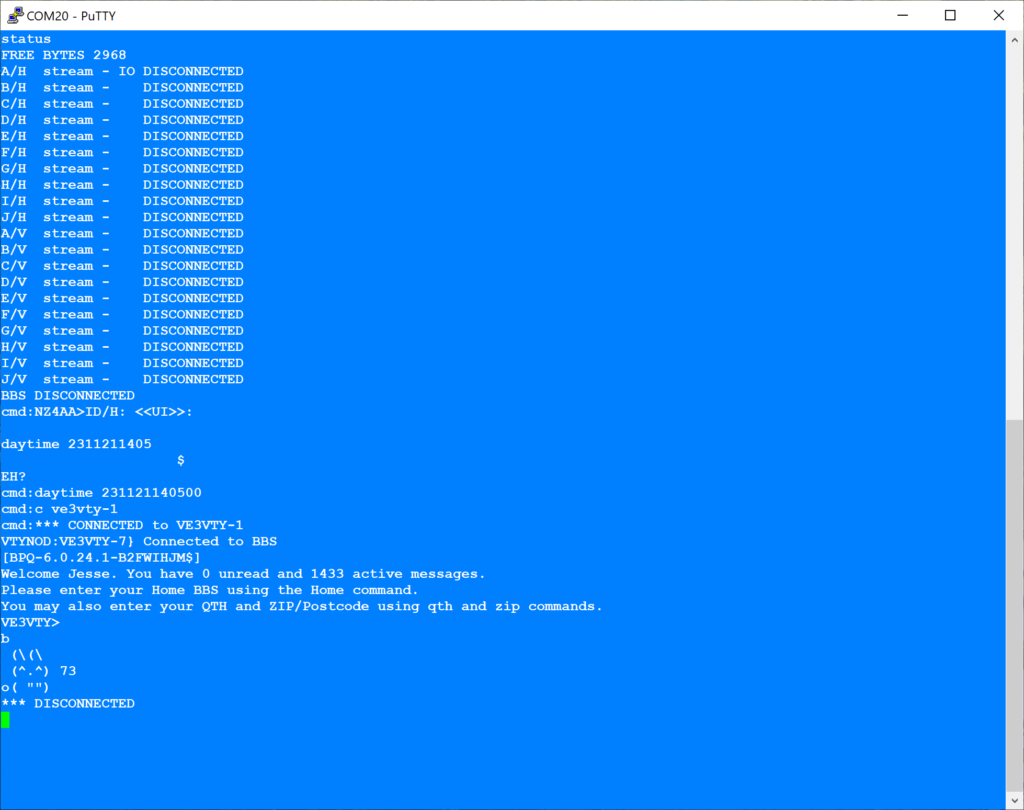
The selected stream and stream status can be shown using the STATUS command:

In the example above, the IO is set to the first HF stream. This means commands to connect, disconnect, etc will be directed to the A stream for the HF port. The first 10 streams are for the HF port, the second 10 streams are for the VHF port.
Many of the standard commands such as BEACON have directives for each port as an option. For example, BEACON 60/120 would set the HF side to beacon every 600 seconds and the VHF side every 1200 seconds.
Trouble Decoding Packets
After leaving the TNC listening on 14.105 for a few days, and using the MHEARD command to check in to see who the TNC heard, it was empty. Even though I heard packets being transmitted, the TNC did not decode any of them. I double checked the MONITOR and MALL options several times.
I flipped the AM/FM switch on the front panel from AM to FM. Suddenly the carrier detect light illuminated and packets were shown on the terminal. Success!
After a few minutes of monitoring on 20 meters (14.105 LSB), I was able to decode several stations:
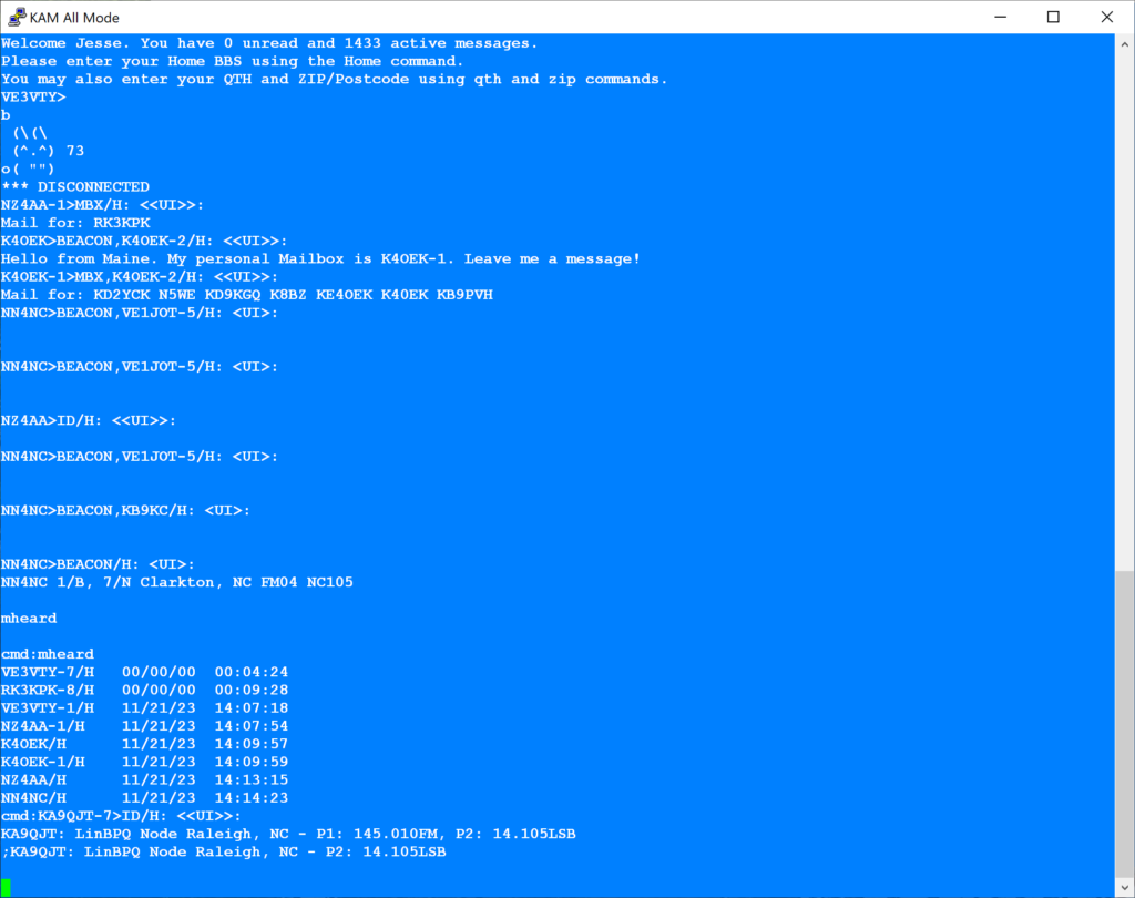
I then tried to connect to VE3VTY:
I was able to successfully connect to VE3VTY-1 on 20 meters (14.105 LSB) with 30 watts output power, which is about 400 miles from my QTH. Not too bad for 30 watts and a dipole.
I am not completely sure what the TNC is doing with the AM/FM selector switch, but the user guide explains this setting vaguely as “limiters”:

Firmware
As with any device with a microprocessor, there is a firmware release history. These days firmware can be updated via USB, serial port, online, or other electronic means. However, older vintage hardware used EEPROMs or FLASH devices, depending on the era. These needed to be physically swapped out for the firmware updates.
The version that was in the TNC from eBay was version 2.85, and the most recent version for this hardware was 6.1. Since Kantronics discontinued the KAM long ago, and no longer offer firmware updates for sale, other options are available, including eBay. I found and ordered a version 6.1 firmware, which included the larger sized serial EEPROM where user settings are saved to when issuing the PERM command.
Replacing the firmware and EEPROM were fairly simple. I no longer have a chip puller tool, but I used a small flat screwdriver to carefully lift each corner on each IC a little bit at a time to avoid bending the leads. The instructions that came with this updated firmware mentioned a possible jumper change needed.
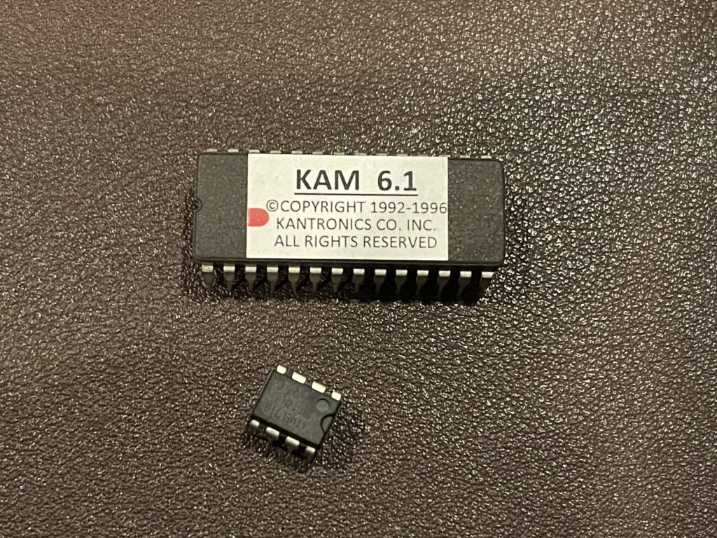
The lower boxed jumper area in the picture above, labeled X was set to 2 (top two pins shorted). It was suggested in the instructions to move this to short pins 1 and 2.
Then, it was recommended that the hard reset and test be performed, by moving jumper K6 to T. I did this, and received an EEPROM failure message. I then moved the X jumper back to the previous position, and then received a PASS on the self-test.
On power up in normal operating mode, version 6.1 was displayed on the startup message. I reset all of my settings and preferences, issued the PERM command and recycled the power to see if the settings were saved.
Note: The voltage regulator IC on the front of the PCB can overheat quickly, depending on the input voltage to the TNC. Avoid powering the TNC PCB more than 30 seconds or so outside of the case. The case acts as a heat sink for this IC.
Correct User Guide
I had been using the guide I found online, version D (2.7) dated August 1987. It seemed like this manual was incomplete, with several missing references, a bit out of order, etc.
After the firmware update, I found another guide, version 3.0 dated August 13, 1990.
Lastly, I found a more recent update for PACTOR, dated November 12, 1992.
Updated Features
After a quick comparison between the two user guides, it appears the following was updated:
- PBBS
- KA-Node
- Host Mode*
- NAVTEX*
- WEFAX*
- PACTOR*
* Features added that were not present at all in previous firmware, version 2.85.
VHF Packet
I was able to use this TNC for VHF packet in addition to HF packet. There are two ports on the back of the TNC, one for HF and one for VHF. The HF port was the primary use and focus in this post. However, since I had been using the KPC-3 (a VHF TNC), I tested the VHF side of this TNC by moving the radio connection from the KPC-3 over to the VHF port on this TNC (they both use the same pinout and connector type).
I switched the A/B switch to “A”, the VHF side and changed I/O streams on the TNC to VHF Port “A” via PuTTY. I was able to connect to KD2YCK-1 on VHF and drop a message. If I wish to use this TNC exclusively for both VHF and HF, I would simply use the A/B switch accordingly, to switch in the corresponding radio port to the FT-991A.
Remote Operation
Recently I have added a method to be able to connect to my packet node using a VPN and SSH. This allows me to remote in, check for messages, leave messages, or participate in chat when not physically at the keyboard in the packet station.
I have posted an article on the method I used to implement remote operation,
Final Thoughts
It’s always fun to discover a new mode on the air, and even better when you find that there are enthusiasts using that mode frequently. In this case, extending packet onto HF was a bit of a challenge at first, but well worth the effort.
I’m glad I was able to find some vintage hardware, the KAM All Mode TNC, and at a reasonable price. I was also glad to find the 6.1 firmware (most recent). This allows me to try PACTOR and some of the other modes this TNC supports.
After a few days of listening on 14.105, I heard CT1EBQ-1 in Portugal, N0HI-7 in CO, and AB4KR-7 in FL, in addition to KD2YCK-1 next door.
I plan to use the TRS-80 Model 100 on this TNC for some automation of alerting when new stations are heard, and other tasks. Interestingly, the TNC user guide specifically mentions this vintage laptop as well as the C64.
If you’re interested in HF packet, there is a group of HF Packet enthusiasts, Network 105, who have set up a mailing list and page for information.
Update
When first setting up the TNC, I found that I was hearing quite a bit of packet activity on 14.105 LSB for example. However, many were not decoded by the KAM. Hearing so much packet activity and not seeing much of it decoded left me wondering whether the TNC was faulty, an audio level wasn’t quite right, or packet just wasn’t as feasible on HF versus VHF.
Connections to many nodes were not possible for me, and it seemed that there was something not optimal in my setup.
Many months later, I raised an outdoor HF antenna, and this improved my ability to decode and connect to HF stations. For the most part, if I could hear it, it was now decoded by the TNC.
What I suspect the issue was is noise. The indoor antenna picked up more noise from internal sources, which interfered just enough with packet to affect decoding ability. My noise floor from the indoor antenna was quite high compared to the outdoor antenna.