
Raising My First Outdoor HF Antenna
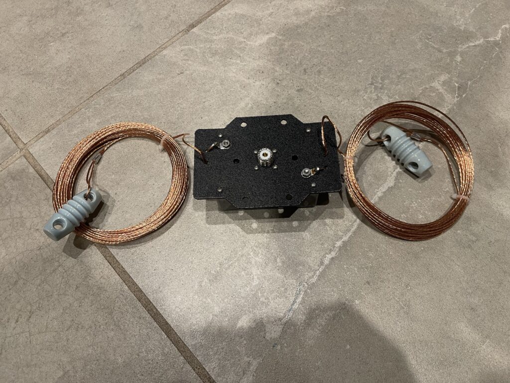
When I first got on HF, I used an off-center fed dipole (OCFD), the MFJ-2012. This antenna is a multi-band antenna covering 40, 20, 10 and 6 meters. It’s rated at 1,500 watts PEP for phone and CW, and half of that for RTTY, FT8, and other digital modes or high duty cycle modes.
I chose this version of their OCFD as opposed to the MFJ-2010 which is rated for 300 watts PEP. Since these ratings seem to be dependent on duty cycle, I wanted to be sure that my antenna can easily handle higher duty cycles at my wattage level without having to worry about overheating the core in the matching transformer.
I am currently running only 100 watts PEP and I run only 30 watts or less on digital modes. This antenna will easily handle this type of usage. I am a bit skeptical that this antenna would handle 1,500 watts PEP, specifically the balun. I built an RF Kits end-fed half wave 49:1 balun and it is quite a bit heftier than this one appears to be.
First Antenna Indoors
I did not put up the OCFD outdoors, I put it up in the attic. I strung it from end to end to raise as much as possible (as much as would fit), but I was short of attic space by about 8 feet on both ends.
I folded the ends downward along the wall and roof line, and kept the ends insulated from anything nearby. The antenna worked quite well, as I was able to make confirmed contacts (FT8) to over 85 DXCC entities, most of which I made on 10-meters at 30 watts or less.
Since this OCFD is multi-band, the height of the antenna is really only optimal for a single band at any given time. Unless someone comes up with a clever way to raise or lower the antenna based on operating band, for now, it remains at a fixed height, at approximately 30 feet.
Limitations of an Indoor Antenna
My concerns for an indoor HF antenna were primarily reduced height, the folded ends, and the roof material. There is also quite a bit of sheet metal and ducting for air conditioning up there in the attic. All of these things can affect an HF antenna.
The roofing happens to be tile, and I doubt there is anything between the wood I see inside the attic and the tiles outside. There is not likely to be any metal flashing or other materials to be concerned about for RF interference. But, I really do not know for sure what effects this may have on the antenna.
After a few years of decent performance from this HF antenna setup, I was curious if I could do better. I was curious if I put the same antenna outdoors and up a bit higher, if it would improve performance over having the antenna indoors. And if performance was improved, would it be significant or would it be marginal? Without anything to compare the indoor antenna to, it was a big unknown.
Limited Options
The area I live in has very small lots and is crowded by trees, houses, and utility lines. If I were to put up an HF antenna outdoors, it would need to fit within a very small space. I do not have room for an 80 meter dipole for example.
Vertical antennas are best for this type of limitation, but placing a vertical antenna somewhere where kids won’t touch it and where I have space for radials is not an option.
Of course a mag loop antenna would work, but they have a high Q factor, meaning they need tuning every few kHz or so. This limits what you can see on either side of your VFO frequency on a waterfall or panadapter display. Mag loops are quite expensive if they have a built in auto tuner.
I do have an end-fed half wave (EFHW) antenna I built that I could raise, either horizontally or vertically. However, the possibility of higher noise and the potential need for a counterpoise (or RF in the shack) are challenges to solve for with this type of antenna. End-fed antennas have an advantage in that they are easy to put up. The balun is at the end, requiring only two lift points. Perhaps this will be something I try later on.
For the experiment, I chose the same antenna that I have in the attic to compare to, the MFJ-2012. The OCFD is not as ideal to hang as an end-fed antenna due to the balun about 1/3 of the way near the middle of the two ends. An end-fed on the other hand has the balun at the end, making for just two lift points needed, one at each end. They are also a bit more stealthy, as there is no large box hanging near the middle of the span.
To hang the OCFD outdoors, I am using only two lift points, one at each end. The balun and feed line will hang on its own, not supported by any lift point.
Identifying the Trees
Because I chose a horizontally mounted antenna, I would need to raise it up to a decent height, and, have enough space for it to be fully extended end to end in order for it to be an improvement over my current attic antenna.
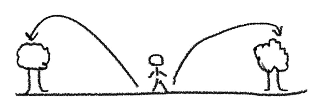
I chose two trees I could use for hanging the antenna.
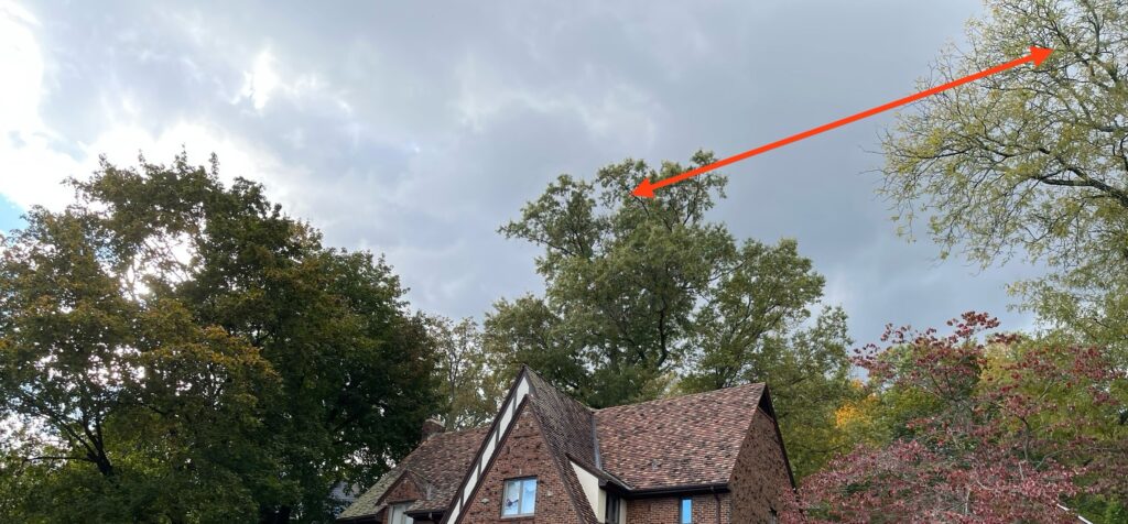
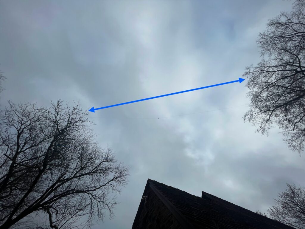
The tree to the left is behind the house and ideal for the short side of the dipole antenna to run the coax down to a lightning arrestor and into the shack. The tree to the right is on the side of the house. At no point would the antenna, rope, or feed line cross over a utility line. The utility line in this case is to the left of the tree on the left, right behind it.
The height on the left side would be about 75 feet, and the right side would be about 45 feet.
Raising the Antenna
I do not climb trees. My options are limited due to space. Near both trees are neighbors’ houses, so a slingshot is not ideal. Neither is using a throw bag.
I thought of a rather odd but possible way to get the antenna up. I could use my DJI Spark drone.
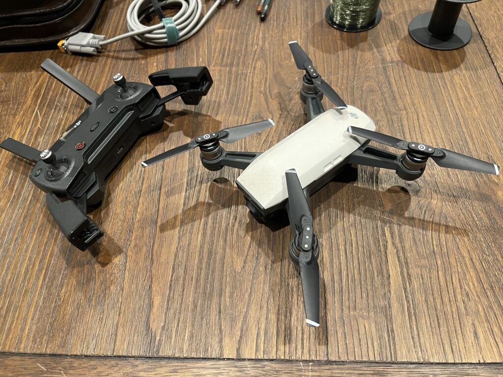
The Spark drone is very small, lightweight and completely unable to lift any significant weight. This means I cannot attach a rope or cord to the drone and lift it up and over a tree.
However, I could attach fishing line to the drone and lift that up and over a tree. Then I could attach rope to the fishing line and pull it through. Then I could use the rope to pull up the antenna.
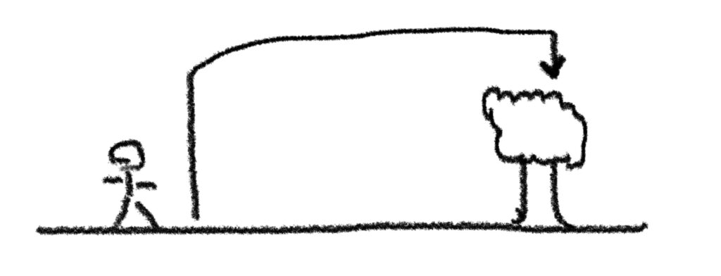
The plan would be to bring the line up from a far side of the tree and drop it straight down the center. In theory, if one leg of the antenna were attached to this far end of the line and raised by pulling it up from the other end of the line which is through the center of the tree, it would be clear of branches in between when raised.
The same can be done for the other tree. The idea would be to attach each end of the antenna to the long side of each line pulled over the trees.
“Release” Method
If I attach fishing line to the Spark drone, how would I land the drone on the other side of the tree without it getting caught in the propellers? The Spark can’t lift any weight, so one of those remote controlled drop/release boxes won’t work for this drone.
What I ended up with is a method to loosely attach the fishing line to the bottom of the drone, and give it a slight tug when I want to release it.
In order to get the fishing line on the drone end to fall to the ground after releasing it, I needed a weight heavy enough to fall through the tree pulling with it the fishing line, but not too heavy for the drone to lift. Also, the weight needed to stay attached and not fall off prematurely.
This was all a bit of a stretch, but worth a try. Note that what I am explaining here is risky, can damage property or injure someone, so attempt at your own risk. I attempted all activity mentioned here without persons underneath or near anything being lifted. Further, the drone was never flown over a person or property. I will explain why this was important.
Perfect Weight
For a weight, I took out a bolt and a nut that together would make an ideal weight. The ideal weight was something the Spark could lift without affecting the safety of the flight, but also heavy enough to fall through the trees after being released from the drone.

I used some clear tape and affixed a short tail of the fishing line to the bottom of the drone, with enough slack so that the bolt is hanging close to the center of gravity. This way, the effects of carrying the extra weight are minimized.
I was careful to apply the tape in such a way that it was possible to give the line a tug or two to release the bolt, but not fall off prematurely.
Trial and Error
I took the larger taller tree as the first tree to tackle. I have only a 15 minute maximum flight time per battery, realistically only about 12 minutes reliably. In my area, GPS lock takes a bit of time, and the drone drains quickly. I take off, hover in place about 10 feet off the ground, and when GPS is locked I can begin.
It took quite a few attempts, at least 4 or 5. One time the bolt dropped prematurely, other times the bolt fell through the tree after a quick tug on the line, but not far enough into the center of the tree around a large enough branch. This is why it was important to not fly over property or people. This method was not controllable and a falling bolt from 100 feet up can cause an injury or damage to property.
Sometimes the bolt would drop through the tree a few dozen feet, but stop, and not reach the ground. I would tug the line a bit, coaxing the bolt to drop further down, watching for where it ended up.
On about the 4th or 5th attempt, I finally got the bolt straight down the center of the tree, around a good sized branch near the top.
I kept the far end of the fishing line tied down while I went over to the bolt end of the line, near the center of the tree, on the ground. I attached lightweight UV resistant nylon 1/8” white rope to the end where the bolt was. I then went to the long side and slowly raised the rope up the center of the tree and over the top until it reached me.
Success! I had a reasonably strong piece of rope all the way up and around the tree. I kept the long end tied down far enough away so that the rope wouldn’t blow around and get caught up in the side branches. When I raise each end of the antenna, I am aiming for the ends to come up clear toward the top of the tree, and not get snagged up on the side branches.
I repeated the process on the other tree. I then attached a 16oz throw weight to the two long ends of the rope. This was the approximate center point for the two sides. I then tied down one end and raised the other. I did this to test out the hoisting up process to see if the end result would be free of the lower branches.

Preparing the Antenna
Now that I had the ropes up and tested that they were free and clear of branches when raised, I can begin working on the antenna.
Since this is a semi-permanent installation, I need to take specific steps in the installation to ensure safe operation and as apply as much weatherproofing as is feasible.
Feed Line
I need to feed the antenna with enough coax to reach from the feed point to the ground where the ground rod will be driven. This will be near the entrance to the shack.
I chose LMR-240 Ultra Flex from Times Microwave. This coax is sized the same as RG-8X, which is convenient because I can use the same PL-259 crimp connectors I am familiar with using. My thinking for using Ultra Flex was to help avoid damage to the coax from repeated wind movement of the coax in the air.
I ordered a 150 foot length, hoping that would be enough to get down to the ground rod location. I started with what I thought was a 75 foot piece, but it was way too short.
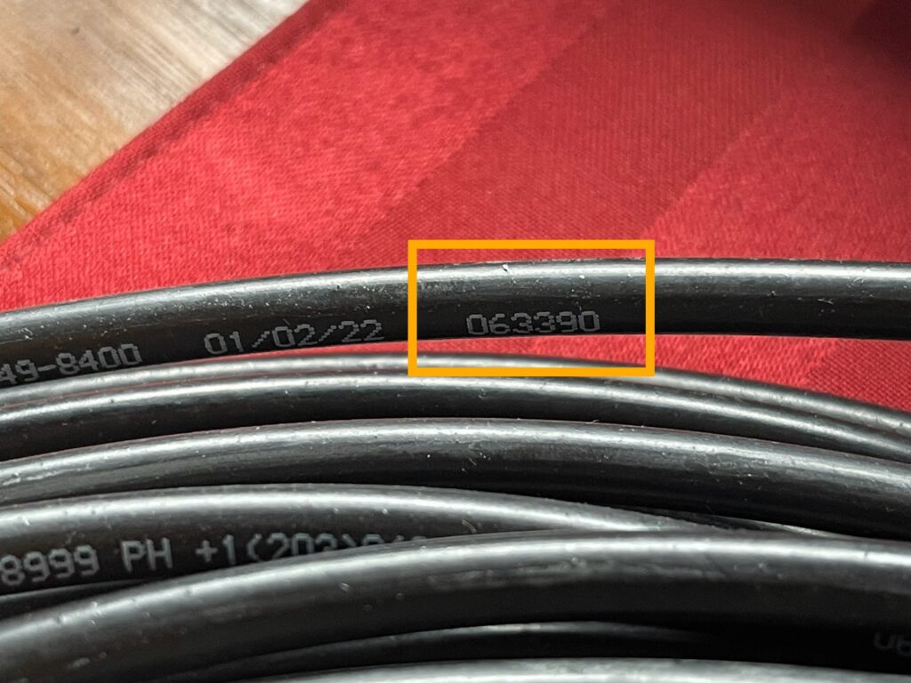
I must have cut a few feet off a 75 foot section for jumper cables at some point. With Times Microwave coax (and some other brands as well), there is a marker number at every foot. If you take note of the number at each end, subtract them, you will get the length in feet.

The advantage of this coax is slightly lower loss over RG-8X with a more flexible stranded core.
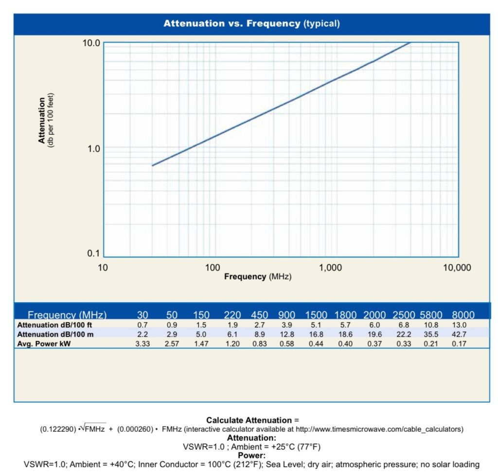
Since I’m feeding an HF antenna, and most of my HF activity will be below 30 MHz, this coax will be good enough, compared to LMR-400 for example. At a length of 100 ft, the loss at HF would be only 1.6 dB.
When comparing this coax to LMR-400 below 30 MHz, LMR-400 has only a 0.7 dB loss at the same length:

For comparison, regular RG-8X has a 2.0 dB loss at 100 ft of length for frequencies below 30 MHz.
Lifting up 75+ feet of LMR-400 is not something I wanted to do for this installation. The rope is not exactly secured directly to the strongest branches of either tree. I do not have a way to secure the coax. It will be hanging from the dipole at the feed point.
When I put up my VHF / UHF antenna, I used LMR-400, and it is not exactly lightweight, not to mention the stress on the connector at the feed point if it were used to feed this type of antenna without support. On my VHF / UHF antenna, it was secured to a wall on the way up and enters into the attic before connecting to the antenna.
Using LMR-240 Ultra Flex is light weight at only 0.034 lbs per foot. Assuming 75 feet of the coax is in the air hanging from the feed point of the dipole, that’s only 2.55 lbs of coax dangling.
Coax Connectors
At some point any outdoor antenna setup will require installation of at least one connector. Unless you have the ability to run a length of pre-made coax with connectors on both ends from the antenna to your radio, you will need to install connectors yourself.
Coax with connectors installed is far more expensive than putting them on yourself. Most of the time the length needed for coax is not exactly known until the coax is fed from the antenna to the radio. At that point you may cut most of the excess off.
Installing connectors yourself does require a small investment in tools and some experience. Properly installing a connector is necessary for the performance of the feed line and for a long lasting and durable connection.
For connectors, I use the PL-259 crimp and solder style from DX Engineering:

The connectors must match the type of coax they are being fastened to. They are sized to match the coax.
There are also different types of connectors which fasten either by crimping, soldering, or both, depending on the type. In my case, the connectors I use require soldering the center connector and a crimp on the braid. I’ve heard that a crimp for the braid makes for a better connection than a solder style connection.
I have a coax crimper kit that comes with cutters, two strippers, and a crimper. I’ve put so many connectors on coax by now that this kit was well worth the price.
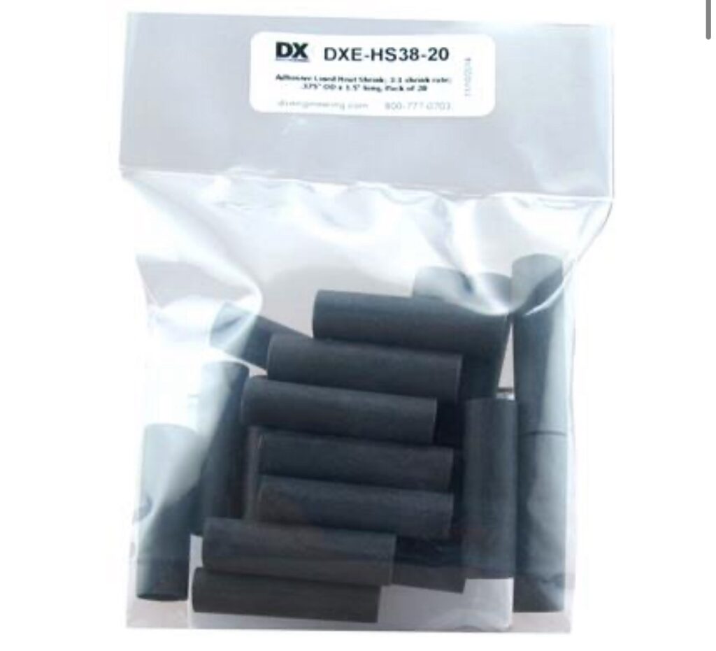
After crimping, I secure the connection with heat shrink. I prefer the DX Engineering coax heat shrink because it has a bit of glue which is activated with heat, providing stronger protection for the PL-259 crimp connector.
I now have 150 feet of coax with connectors for testing the antenna:

Yes, I did solder connections onto my coax before running it through the exterior wall. I did this because I wanted to test the antenna before making it a semi-permanent installation.
If the outdoor antenna is not an improvement, then I would not bother running coax through the wall into the shack. If it is an improvement, then I could cut off the connector and attach a new one after running it through the wall.
What I usually do is cut off several feet with the connector so that I can use the cut off section as a jumper cable later on.
Weatherizing
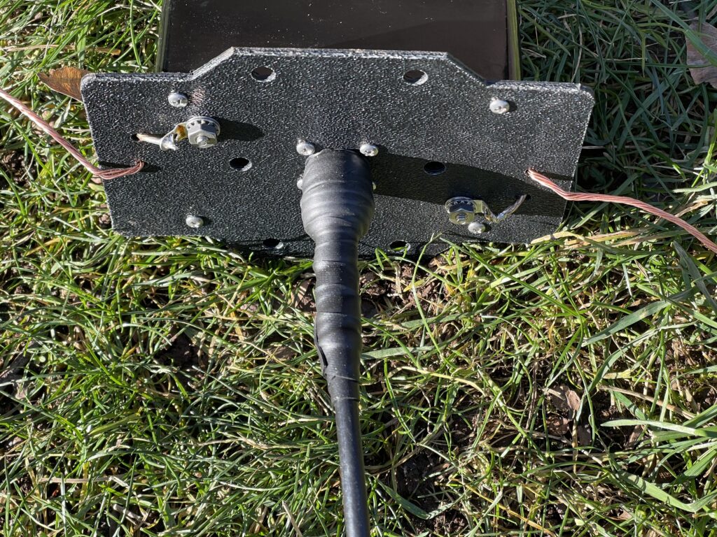
The MFJ-2012 antenna has the SO-239 connector (feed point) on the under side of the balun box. This is convenient for keeping water out, but a good seal around the feed line connection is necessary. Moisture and water destroy coax rather quickly.
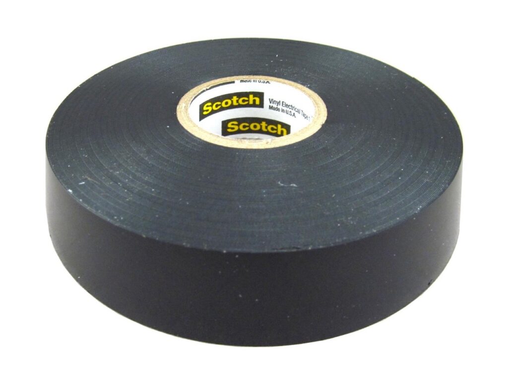
I used 3M 2155 Temflex tape for the connector seal:
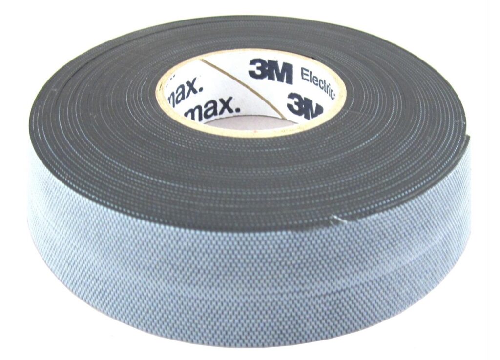
This tape adheres to itself, which is why it is rolled up with an insulating layer. The tape is stretched over starting at the coax and wrapped upward onto the PL-259 connector for a water tight seal. It’s also a good idea to apply a small amount of dielectric grease to the SO-239 threads to help seal against moisture.
The seal will be reasonably water tight, but not air tight. The dielectric grease will help keep moisture from the air out. Temperature and humidity changes result in moisture or condensation seeping into the connector and balun box.
Temflex is not UV resistant, so after applying the Temflex, I applied a layer of UV resistant electrical tape over the Temflex.
I repeated this process of sealing each outdoor connection, both at the feed point on the antenna, and at the lighting arrestor.
Note that the balun box has ventilation holes in the bottom. This is to allow airflow between the outside and inside of the box. This prevents condensation from accumulating inside the box due to humidity and temperature changes. After raising the antenna, the weight of the coax ensures the box is oriented with these holes on the bottom.
Rain should stay outside of the box, unless it suddenly falls upward from the ground.
Raising the Antenna
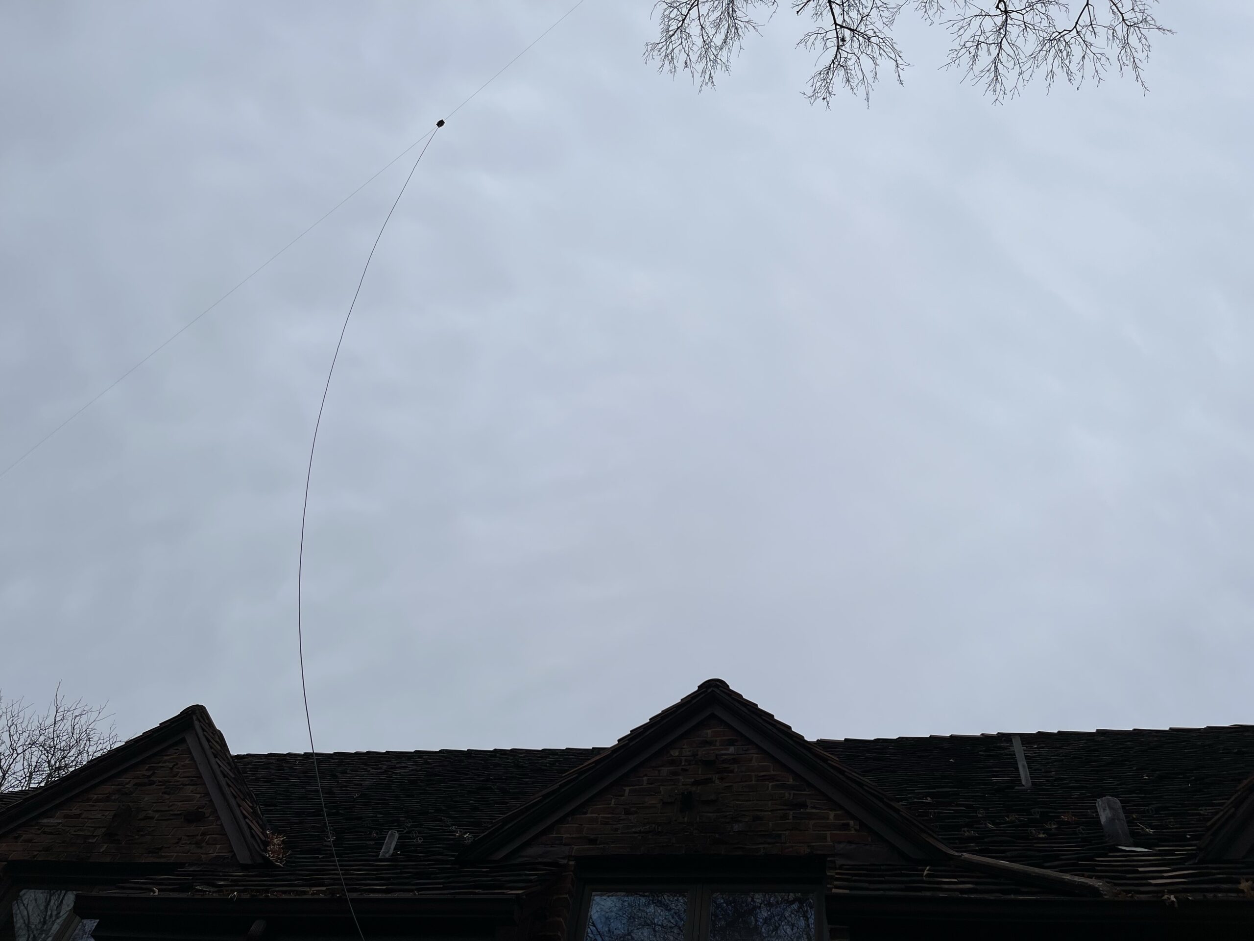
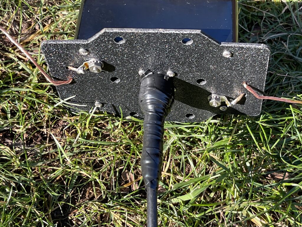
I attached each end of the antenna to the ropes from each tree, attached and sealed the coax connector, and slowly raised each end.
It took a bit of time to work the antenna around the roof line and to get it pulled over as much to the tree on the left as possible. This kept the balun box mostly to the left, hoping it will be less noticeable.
Testing
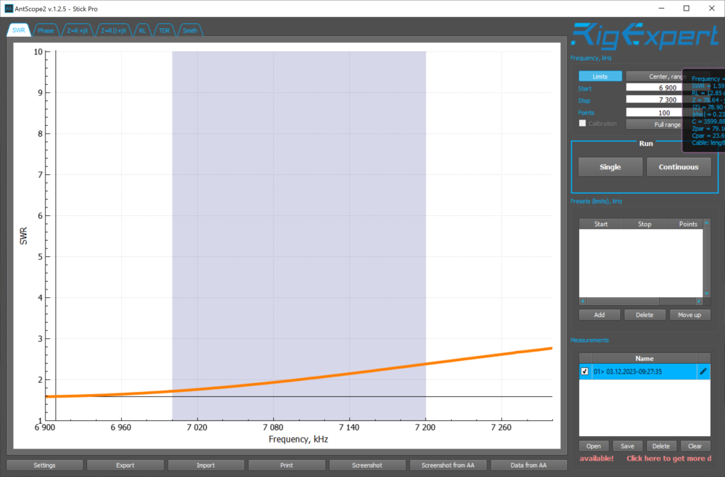
Before finalizing the installation with the antenna raised, I measured the SWR with an antenna analyzer. I wanted to make sure I wasn’t dealing with unusually high SWR on the bands the antenna is supposed to be resonant on.
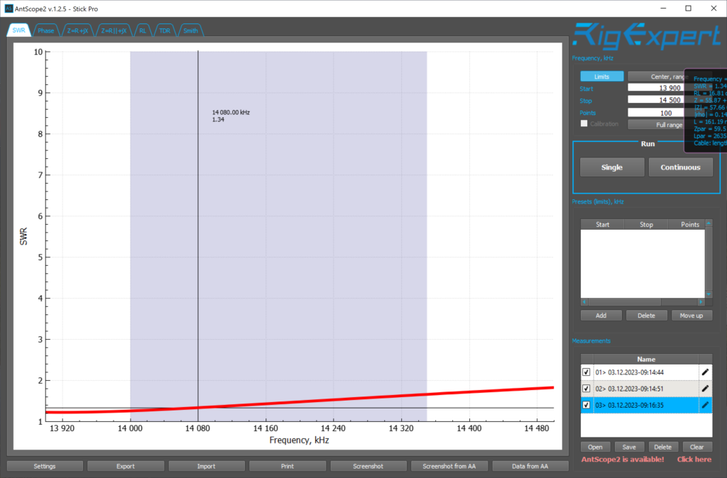
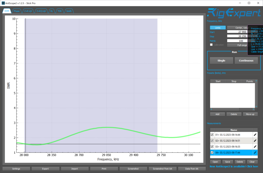

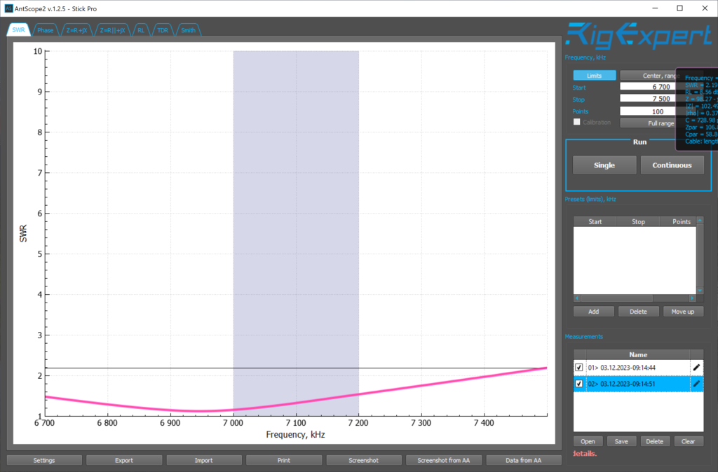
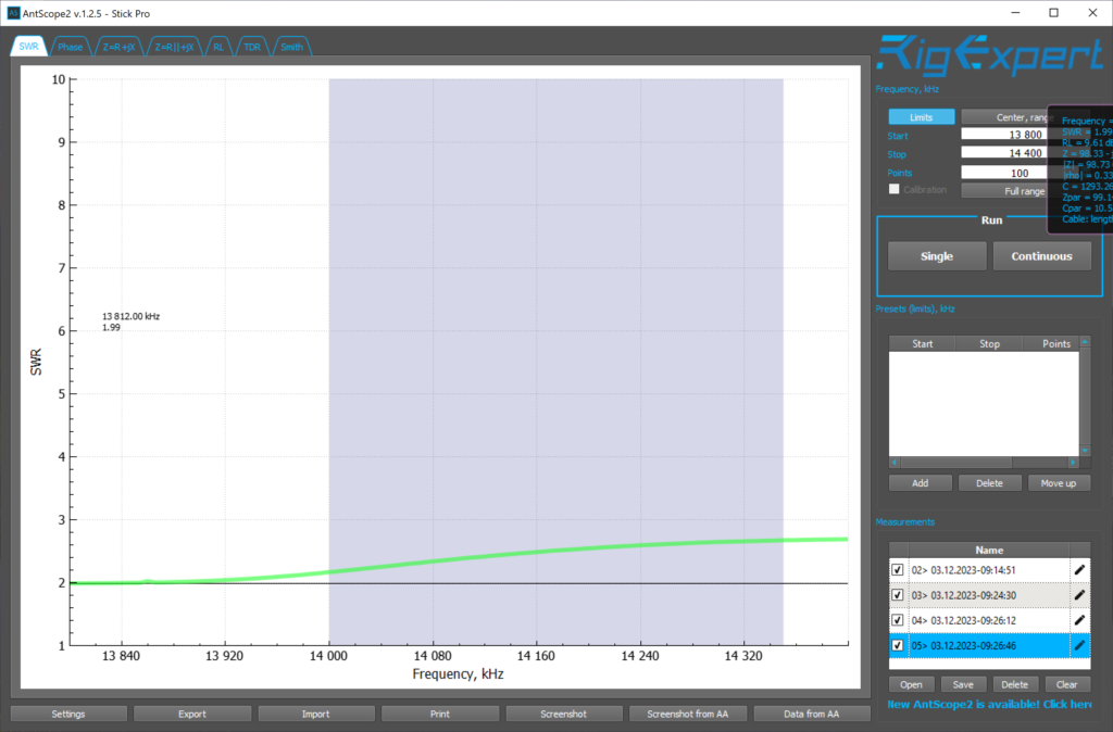
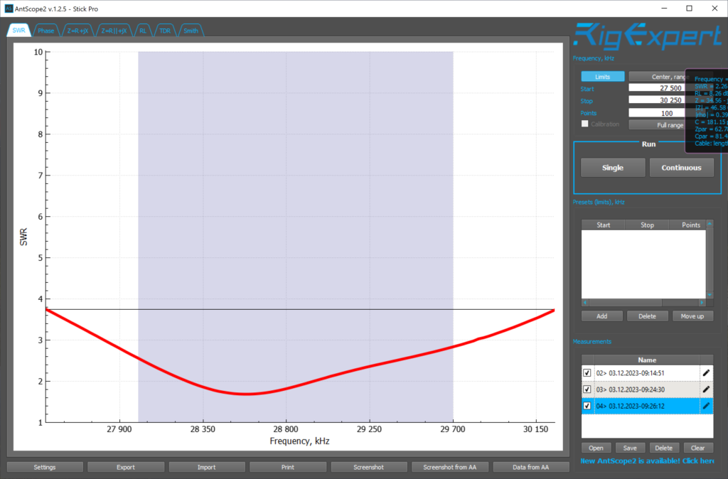
The SWR was well below 1.5:1 for the lower portion of the 40 and 20 meter band, and very good for the rest of the 40 and 20 meter bands. The lower portion of the 10 and 6 meter bands were also good, around 1.5:1 each. I was suprised to see such good results without a tuner. This MFJ OCFD is not adjustable in terms of length.
I could get away without the tuner if needed which would allow me to use my WSPR beacon and band hop. With the old indoor antenna, I would need to tune most of the time using the manual tuner. The WSPR beacon does not emit enough power for an auto tuner. If I changed bands, I would need to manually set the tuner to match.
The attic installation did not have such good results, which is why I purchased the tuner back then:

After measuring the SWR with the antenna analyzer, I ran the coax into the shack through the door to start testing with the HF rigs. I wanted to test the antenna before routing the coax through the exterior wall, through a lightning arrestor, etc.
I repeated the process of using my antenna tuner and antenna analyzer on each band and measuring for a 1:1 SWR and noting the inductor, transmitter and antenna dial markers for each.
I use a manual tuner (MFJ-969) and use a printed spreadsheet as a reference to where the dials need to be for a given band and band segment. This is needed only because I want to fine tune the SWR a bit. I have quite a few HF transmitters running through that tuner and out to the antenna. Only one of them has a built in tuner which I do not use.
When I connected the new antenna to my HF rigs, I noticed right away a lower noise floor, and signal strength was about 3 S units higher than with the old antenna. Since my tuner has two coax connectors (for two antennas), I can switch between A and B very easily and compare the receive between the two antennas.
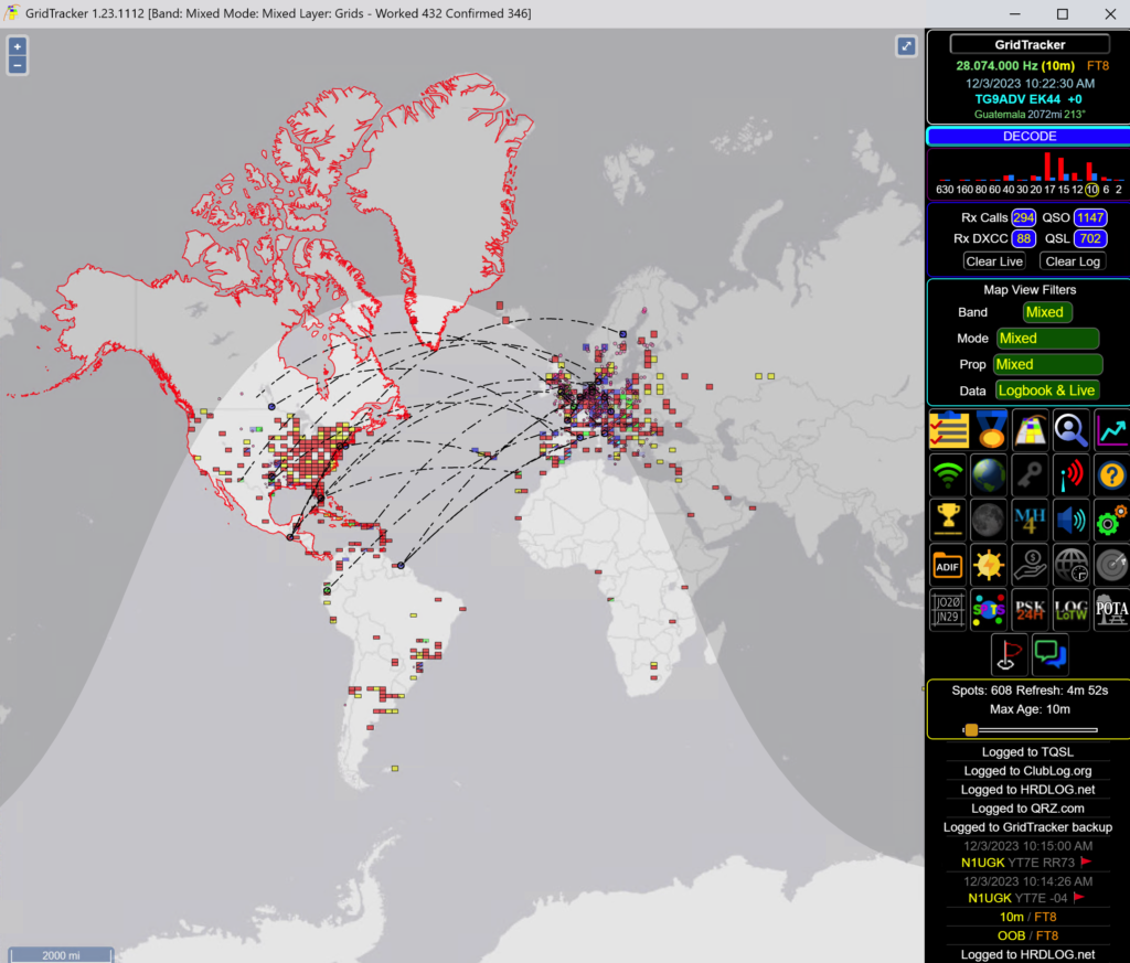
For transmit testing, I started at night, testing on 20, 30, and 40 meters FT8. On 20, on my first CQ I see a spotter in Western Australia. On 40, I saw 250+ spotters on the first CQ. The next morning 10 meters was open, so I sent out a few CQs on 10 meters and saw just over 600 spotters.
A bit later in the day I tested FT8 on 20 meters to see if I can get to Australia:
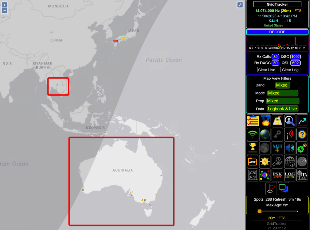
About a dozen spots reported from OC and even a spot in Thailand. I was never able to reach Australia at 4PM on FT8, only via my WSPR beacon rarely, if I ran it for a few days.
On 40, 20, and 10 meters, if I sent out a few CQs and waited for the spot refresh, I would see 400-600+ spots on each band. With the old antenna I would see 200 at most.
Phone (voice) tests with a local station KD2YCK also proved to show a dramatic improvement. We tested phone on 6 and 10 meters. In both cases I would switch between A and B and the receive difference was significant. With the old antenna, the signal was barely above the noise. We were using low power, 10 watts or less in our tests.
Finally, we tested the high bands version of the (tr)uSDX on 10 meters, using low power mode via the USB jack. When powered via USB, my output power is 500 mw peak. We had a perfectly readable QSO. When switching to the old antenna, I was unable to copy KD2YCK from the noise.
Analysis and Comparison
After spending a little over 24 hours with the new setup, already some immediate observations were clear. First, noise was significantly lower. Second, signals were in most cases, significantly stronger. Third, transmit tests on FT8 indicated a significant improvement. Fourth, less “tuning” was needed on almost every band, except 6 meters.
The comparison was easy – the antennas are the same model, one outdoors, one indoors. Having the A/B selection on the tuner made comparisons easy. Using FT8 for testing transmitting via spot reporting and for receive were extremely helpful in comparing the two antennas.
For both the transmit and receive to be significantly improved given the coax differences is striking. For example, the old (indoor) antenna is fed with 75 feet of LMR-400. LMR-400 at HF (below 30 MHz) has a rating of 0.7 dB of loss per 100 ft. The new antenna is fed with twice that length, 150 feet of LMR-240 UF, which has a rating of 1.6 dB of loss per 100 ft. The new antenna has twice the length of feed line at more than double the loss rating, yet it performs significantly better.
Finalizing the Installation
Since the outdoor antenna performed significantly better than the indoor one, it is clear that this one will replace it. The next steps are to finalize the installation.
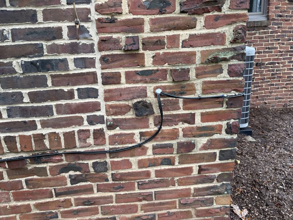
I needed to run the feed line through an exterior wall and secure as much of it to the exterior as possible. I had some help running the coax through an exterior brick wall. I ran 2 lines of coax through, in case I want to raise a second antenna in the future.
Lightning Arrestor
It is recommended by many, if not most, to place a “lightning arrestor” inline with the feed line before it enters the shack.

I’m using the term “lightning arrestor” in quotes because it makes no such claim to prevent lightning from damaging equipment connected to the other end of the feed line. However, these devices are the best protection available aside from physically unplugging the coax from the antenna before a lightning storm arrives. A great intro video on lightning arrestors by Dave Cassler was published by the ARRL.
These are installed in-line with the coax and bonded to ground. The ground bonding is done using the supplied threaded bolt, nut, and lock washer. The ground should be a solid ground rod driven sufficiently into the ground, such as a utility ground rod. I had one driven into the ground near the entrance to the shack.
These work by using a gas-filled chamber or cartridge (arc-plug) which arcs when sufficient voltage is presented across the terminals of the arc-plug. It then effectively shorts the center of the feed line to ground. In theory, most of the voltage would be directed to the shield of the coax and grounded. The arc-plug may survive more than one surge, but when it fails, there will be either a complete short (by design) or a partial short in the coax. The arc-plug is replaceable.
When looking for a lightning arrestor, look for the frequency range it can handle, the insertion loss, the impedance, breakdown voltage, and how quickly it reacts. The Alpha Delta model TT3G50UHP is rated from 0 to 500 MHz, does not block DC (useful for DC controlled rotors or tuners), breaks down surge voltages to 20 – 30 volts, and reacts in less than 100 nanoseconds. The insertion loss is 0.1 dB for HF.
Lastly, make sure the lightning arrestor can handle the maximum wattage needed. For the TT3G50UHP, it handles 2,000 watts maximum.
Antenna Switches with Arc Plugs
Some antenna switches have lightning or surge protection built in via an Arc Plug. I happen to use Alpha Delta switches and they have surge protection built in.
However, the antenna switch is in the shack, and it’s best to keep lightning outside. Even though the switch I am using has surge protection built in, it’s best to put a lightning arrestor outside, before the coax enters the shack.
Attaching the Lightning Arrestor to the Ground Rod
An easy way to attach the lightning arrestor to the ground rod is by using a copper clamp such as the DX Engineering model shown below, the UCGC-Z:

This clamp attaches to a standard ground rod and provides mounting for up to 6 lightning arrestors.

It is recommended to use a copper anti-seize compound on the stainless steel bolts and threads both on the clamp and the lightning arrestor. This prevents galling which results from dissimilar metals being in contact with stainless steel.
I attached the lightning arrestor to the ground rod and weatherproofed the coax connections in the same way I did with the antenna feed point.
I have 5 more spots on this mounting bracket for more lightning arrestors if needed.
It should be noted that the nuts on this particular hardware kit are not easily reversible. Once they are tightened down, they are there forever. It is possible to back them off a bit so you can remove the mount from the rod, but it is difficult to tighten them down again. Be sure it is oriented the desired way before tightening all the way.
This completed the antenna installation.
Final Thoughts
The outdoor antenna made such a significant difference in performance and I wish I had done it sooner. Up until this point, my entire HF experience was through the antenna in the attic. Having the outdoor antenna was like experiencing HF in a new way.
I now see first hand how the most important component in an amateur station is the antenna. Of course this makes sense when you hear it, and actually experiencing a simple or basic change – such as putting the antenna outdoors – makes the effort worthwhile.
Although my particular installation is not perfect, and is not as permanent as it could be, it is an incremental improvement over what I had. I am sure I will continue to make improvements over time. For example, I will need to raise a pulley and use a weight on at least one end to allow for some flexibility that avoids friction between the rope and the tree branch for windy conditions.
This was a far better investment in both money and time than any other investment such as a better rig or an amplifier. In terms of cost, it was mostly time. I did get help with running the coax through an exterior wall and with the ground rod installation.
After a few days on the air with the new antenna, I was able to grab a few more DXCC entities to reach the 100 mark to earn my mixed mode award.
It was great to be able to transmit anywhere on the 40 meter and 20 meter bands without having to use a tuner. I can even transmit on the digital portion of the 10 meter band without the tuner. This allows me to switch bands quickly and easily for FT8 for example. With the indoor version, I would need to adjust the tuner not only per band but for each segment of each band. I still need the tuner for 6 meters and half of 10 meters, as well as the 12, 15, and 30 meter bands, but that’s expected since the antenna isn’t resonant for those portions of the bands.
While the tuner makes the HF radio happy in terms of SWR, it presents quite a bit of loss compared to an antenna which does not need tuning. This is because of the circulating currents between the antenna feed point and the tuner, which in my case for the attic antenna was 75 feet. The loss rating of the coax reduces the signal with each trip back and forth between the tuner and the antenna.
The MFJ-2012 antenna itself is on the less expensive side, compared to similar antennas made by other manufacturers. The coax was a bit costly, but that was by choice. I am sure that RG-8X would work well and would have cost less. I ended up needing almost the entire 150 foot section of coax to feed the antenna.
Putting up an antenna is a task which requires a wide array of knowledge and experience. Everything from the type of antenna (vertical, dipole, beam, etc), feed line, weatherproofing and safety are all pieces of the puzzle.
Every single one of these pieces of the puzzle could be improved upon. As we know, if you ask an amateur how to do something, you will get a wide variety of answers and suggestions. The best experience is when you can try more than one option and compare the differences yourself.
Updates
Since I wrote this post I have made a few updates to the installation. I added a spring on one side and a weight on the other side. I did this to allow for some flexibility in the span of the antenna should the wind move the branches in either or both trees. This allows for some flexing and a return to a normal tension in the wind.
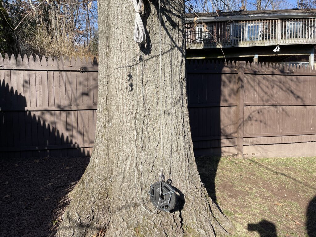
On the weighted side, I added a pulley and suspended a 10 lb weight from the pulley near the ground. This allows for a few feet of “give” should a wind gust move either or both branches. Then, after the gust, the weight will keep the tension on the line.
My next project will be to hang the antenna from pulleys so that the rope is not resting directly on the tree branches on either side. This avoids friction between the rope and the tree branches and would allow for more free movement of the branches during wind.