
RF Kits EFHW Kit
Soon after the ARRL offered the RF Kits end fed half wave (EFHW) kit, I decided to purchase one and give it a try.
My first HF antenna was an OCFD for 40, 20, 10 and 6 meters, the MFJ-2012. I wanted to compare the OCFD with the EFHW antenna to see if there was a noticeable difference between the two. In addition, I could use this for portable operations easier than a dipole.
EFHF antennas are common for field work (as are vertical antennas) as they require only 1 or two hoist points to raise the antenna, as opposed to 3 for a center or off center fed dipole.
The kit came with all of the parts needed for a 40 meter EFHW (66 feet of wire) and the antenna is capable of operation on 40, 20, 15, and 10 meters.
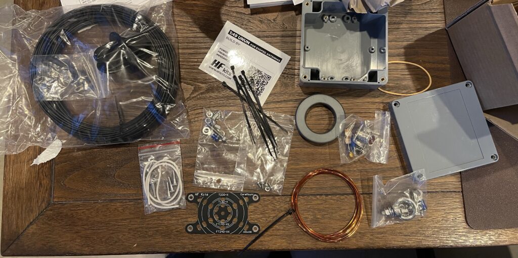
Assembling the Kit
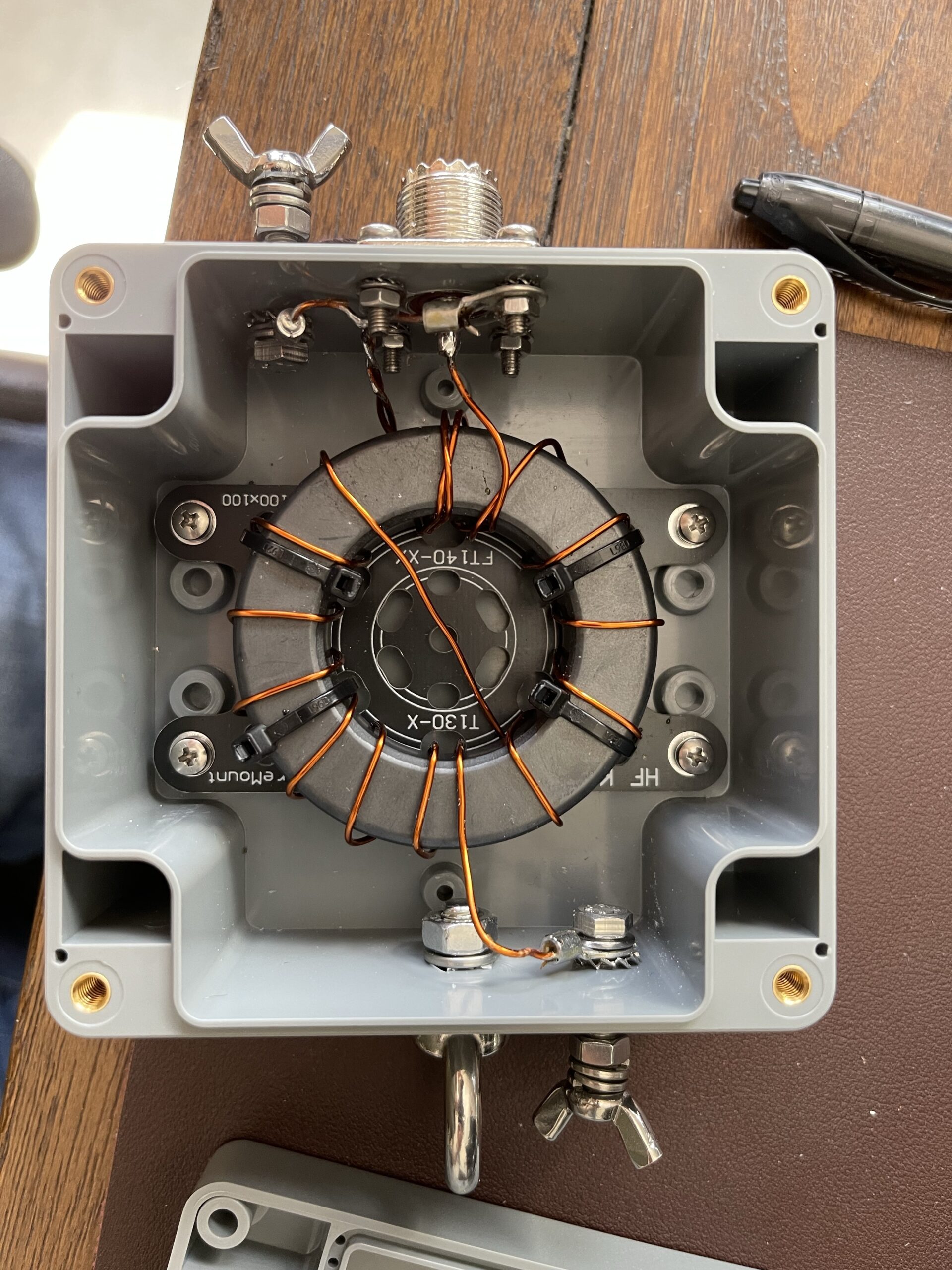
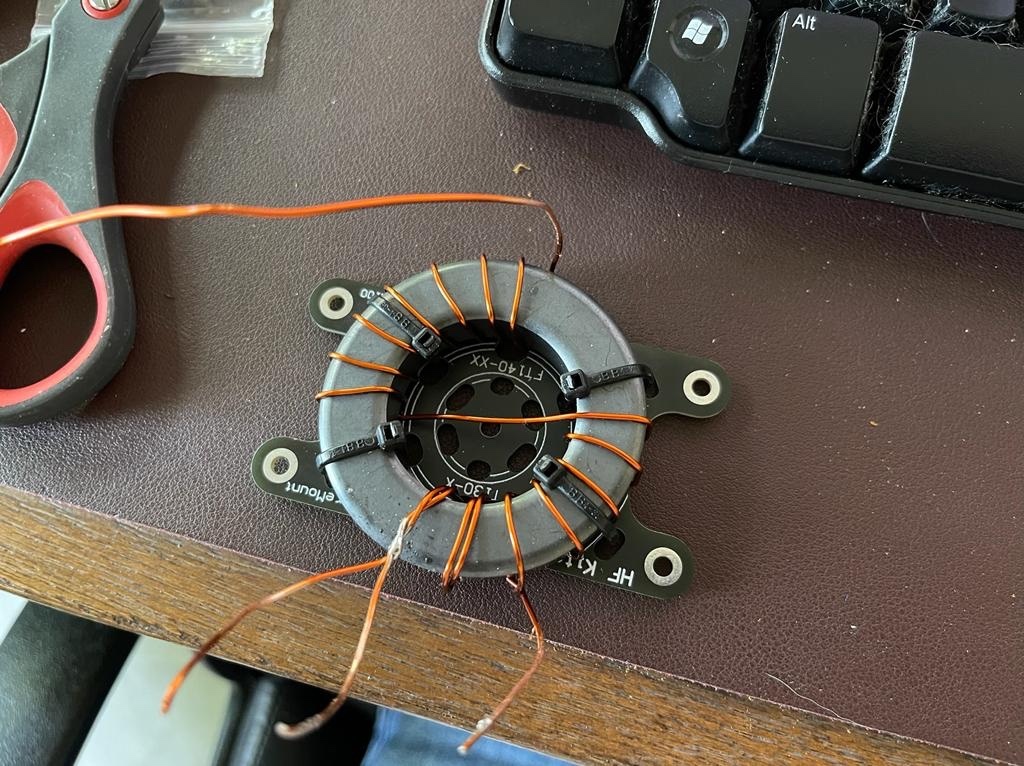
This is the first kit I have built – also the first time I’ve had to wind a toroid. The simple rule for toroids is each time the wire passes through the center, this counts as 1 turn. Once that is understood, then it’s simply a matter of counting each time the wire passes through the center and the spacing of the windings.
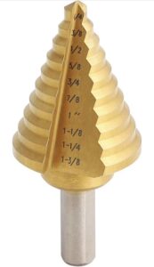
It should be noted that this kit will require you to drill several holes in the balun case, the largest of which is the SO-239 connector. For this, it is recommended to use a step drill bit, which can be found on Amazon among other places.
The unun for this kit is quite hefty, and it’s apparent that it will easily handle the 250 watts it claims to. Winding the toroid was easy, and fairly straightforward.
I decided to add the optional (included) 100 pf capacitor across the center pin of the SO-239 and the ground/counterpoise as I plan to use the antenna for 10 meters.
One thing to note is all of the drilling / hole locations are referenced in metric, cm. Sure, you can do a conversion from the English system if you don’t have a metric ruler, but it’s probably far easier to use a metric ruler.

Testing
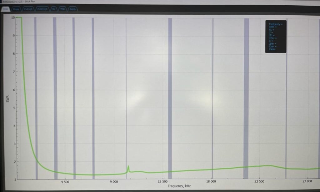
Before attempting any actual transmission using the antenna, I decided to run a sweep on the unun itself, independent of any wire antenna connected to the output. Since the unun is a 49:1 matching transformer, a 50 ohm input would need to have a 2450 ohm output. Therefore, I created an approximately 2400 ohm resistance to connect to the output terminal and ground, which is the same impedance the correct length of wire would ideally be.
When I ran the sweep on the antenna analyzer, I saw a high SWR as if the transformer was not a good match for the 2450 impedance. I was quite puzzled by this. I double checked all of the connections inside the balun box, double checked the turns on the toroid, the solder connections, everything.
I finally realized that the resistors I had used to build a 2400 ohm load were the problem. The resistors I used were wire wound or non-metal film type, which do not work at higher frequency. At high frequency, they act as inductors.
I remade the 2400 ohm load using metal film resistors and the sweep on the antenna analyzer was now indicating the expected result. This test proves the matching transformer is working and simply adding the correct length of wire on the RF output will work as expected.
Counterpoise
There was an article HF kits published which was linked on the assembly instructions for this kit regarding a counterpoise. In theory, the counterpoise can help give the antenna something to work against. If you don’t add a length of wire to the counterpoise connection, or, if that length of wire is not a good match, then the shield of the coax used to feed the antenna will end up as a counterpoise, and will have RF current traveling on the outside of the shield of the coax.
If you run the coax directly into the shack, that could bring RF into the shack. It’s good practice to ground the shield of the coax outside (perhaps at the lightning arrestor for example), before the coax enters the shack. Further, adding a 1:1 current choke before the lightning arrestor. This way, any RF traveling down the coax shield will be terminated at the grounding point, keeping the RF outside of the shack.
Results
For receiving, the EFHW was about the same as the dipole, except slightly more noise. The 1:1 current choke reduced that noise significantly.
For transmitting, the results were also similar. My comparison was FT8 on 20 meters.
My initial results indicated that the EFHW was about the same as the OCFD in terms of performance, at least with 20 meters. This will be a great antenna I can use for portable use in the future.