
FT-991A and TH-9000D with the CX-333 Antenna
After getting back into the hobby and needing a 2-meter and 70-cm base antenna, I chose the Comet CX-333. It is a tri-band antenna which covers 2-meters, 1.25-meters and 70-cm. When I purchased the antenna, I had also purchased the FT-991A which covers HF, 6-meters, 2-meters and 70-cm. I hadn’t yet had a 1.25-meter radio other than a few HTs which covered this band.
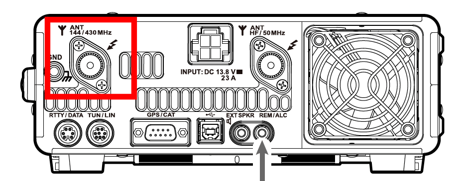
The FT-991A has a single SO-239 connector for 2-meters and 70-cm, and a separate SO-239 connector for the HF side. When I first installed the CX-333, I simply connected the V/U side of the radio directly to the CX-333. I later on purchased a TH-9000D to get on 1.25-meters with a bit more power than an HT. The challenge was, how to I connect this into the CX-333 with the FT-991A already connected to it?
Antenna Switch
There are a few options to be able to use the CX-333 with both the FT-991A and the TH-9000D. The first is to get an antenna switch, and simply switch between the two radios connected to the antenna, such as an Alpha Delta antenna switch.
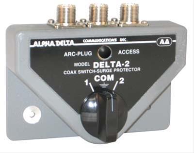
The idea with the antenna switch would be to connect the common to the CX-333, and the FT-991A to one port on the switch, and the TH-9000D to the other port on the switch. Then, depending on whichever radio I were to be using, I could select port 1 or port 2 on the switch. This would work perfectly well with the exception that I would not be able to receive on both the FT-991A and the TH-9000D at the same time. I most often monitor or scan on both rigs at the same time.
Duplexer and Triplexer
Another option would be to use a combination of a duplexer and a triplexer. A duplexer will allow two devices to operate on the same antenna with different frequency ranges. The duplexer provides enough isolation between each radio such that there is no RF energy which can interfere or overload the other device. A triplexer uses the same concept except it provides isolation between three different frequency ranges.
I chose the duplexer and triplexer approach since it would allow for simultaneous use of up to 3 different rigs at the same time with the same antenna.
It should be noted that the CX-333 antenna has a maximum power rating, and transmitting on more than 1 rig at the same time is not advisable if the power rating of the antenna is exceeded. The CX-333 has a maximum power rating of 120 watts. If three 50 watt rigs were to transmit into the antenna at the same time, the power rating of the antenna would be exceeded.
Choosing the Correct Duplexer and Triplexer
Since the CX-333 is a tri-band antenna, I started with the Comet CFX-324 triplexer. This provides a single output to the antenna for all three bands: 2-meters, 1.25-meters and 70-cm and three separate ports, one for each band. Three different rigs can be connected to each one of the inputs: a 2-meter, 1.25-meter, and 70-cm rig and all 3 can be operated simultaneously.
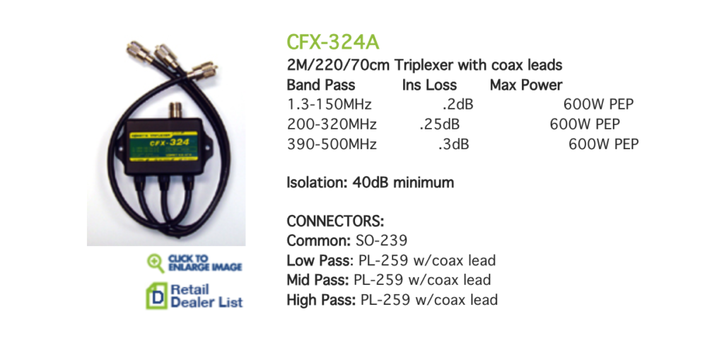
CFX-324 Insertion Loss
The CFX-324A has coax leads with PL-259 connectors, whereas the CFX-324 has an SO-239 connector for the common and PL-259 connectors for the three separate ports. The insertion loss for this triplexer starts at 0.2dB at the low end (150MHz and below), and up to 0.3dB at the high end (500MHz). Insertion loss is something that is also measured and specified for coax switches for example. In the case of an Alpha Delta coax switch, the insertion loss is less than 0.1dB.
CFX-324 Bandpass Specifications
Each of the three ports to the CFX-324 have a defined bandpass, and as illustrated in the image above, each one allows for the corresponding 2-meter, 1.25-meter and 70-cm amateur band allocations I will be using for this antenna.
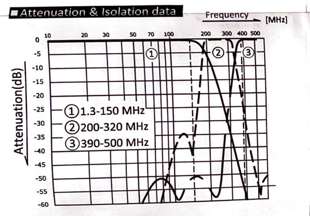
This graph was a bit challenging to read at first. At first glance, it appears that there is overlap from both the 2-meter and 70-cm sides into the middle 1.25-meter section. Overlap would mean that not enough RF attenuation (at least 40dB) is present to isolate the RF from the other ports of the triplexer.
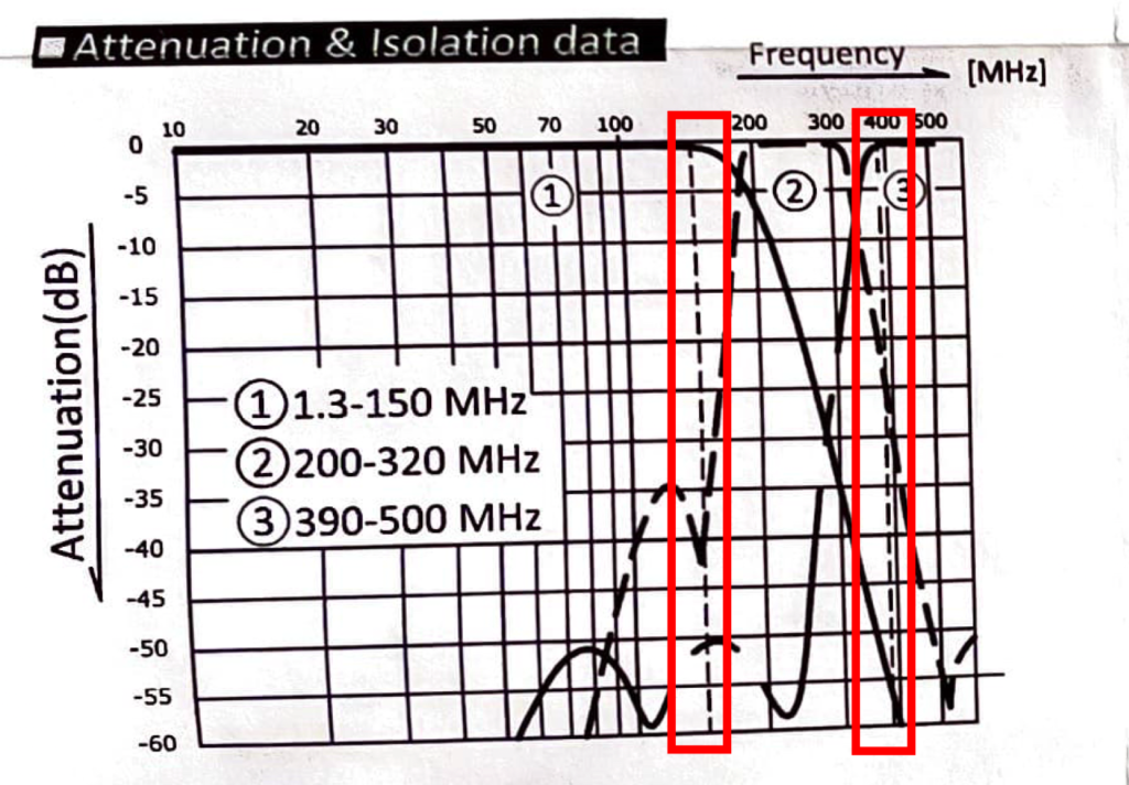
The triplexer is actually a low pass filter for 2-meters, a high pass filter for 70-cm, and a bandpass filter for 1.25-meters. The graph has 2 vertical indicators for 150MHz and 390MHz as these points on the graph didn’t have vertical x-axis markings:
My method for interpreting and understanding this graph was to determine the effective isolation for each of the 3 ports one at a time. For each port, I am assuming a minimum of 40dB attenuation is required to protect the other two receivers on the other 2 ports. I am also taking into account the actual transmission frequency ranges of each rig on each port.
2-Meter RF Isolation
When looking at this triplexer with 2-meter RF power being sent into Port 1, assuming that my 2-meter transmitter cannot transmit beyond 148MHz, I shaded the frequency range in green where that RF power reaches, with respect to Ports 2 and 3 in the triplexer:
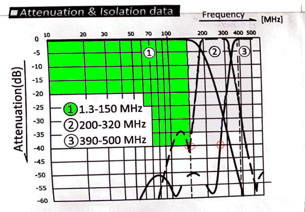
The green shaded area stops when we have at least 40dB of attenuation. We can see Port 2’s bandpass attenuates at a minimum of 40dB right at or around 150Mhz, and since we’re transmitting up to 148Mhz at most on Port 1, there is adequate attenuation protecting Port 2 from that RF power. Port 3 cuts off at 40dB at around 260Mhz. Both of these points are indicated by red circles in the graph above.
It is safe to say that I will have at least 40dB of RF attenuation in Ports 2 and 3 from Port 1. No significant RF power from the 2-meter rig will reach the other 2 ports.
1.25-meter RF Isolation
When looking at this triplexer with 1.25-meter RF power being sent into Port 2, assuming that my 1.25-meter transmitter can transmit between 222MHz and 224Mhz, I shaded the frequency range in blue where that RF power reaches, with respect to Ports 1 and 3 in the triplexer:
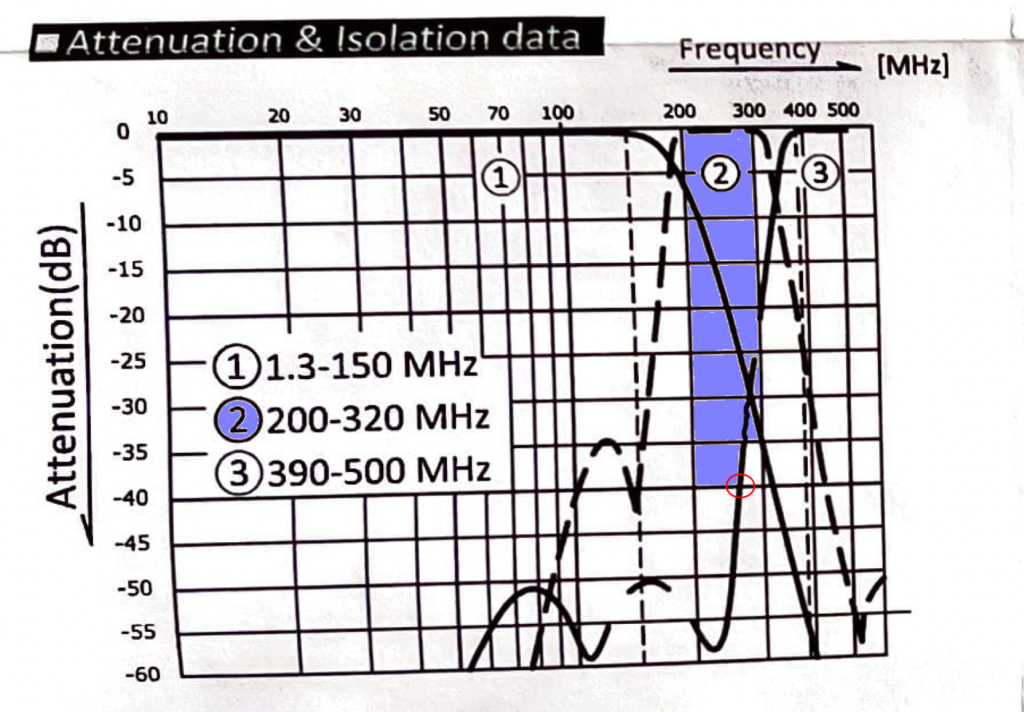
The blue shaded area is actually 200MHz to 300MHz for simplicity of the illustration and stops when we have at least 40dB of attenuation. We can see Port 3’s high pass filter attenuates at a minimum of 40dB right at or around 260Mhz, and since we’re transmitting up to roughly 225Mhz at most on Port 2, there is adequate attenuation protecting Port 3 from that RF power. Port 3 cuts off at 40dB at around 260Mhz or so, indicated by a red circle in the graph above.
It is safe to say that I will have at least 40dB of RF attenuation in Ports 1 and 3 from Port 2. No significant RF power from the 1.25-meter rig will reach the other 2 ports.
70-cm RF Isolation
When looking at this triplexer with 70-cm RF power being sent into Port 3, assuming that my 70-cm transmitter can transmit between 420MHz and 450Mhz, I shaded the frequency range in yellow where that RF power reaches, with respect to Ports 1 and 2 in the triplexer:
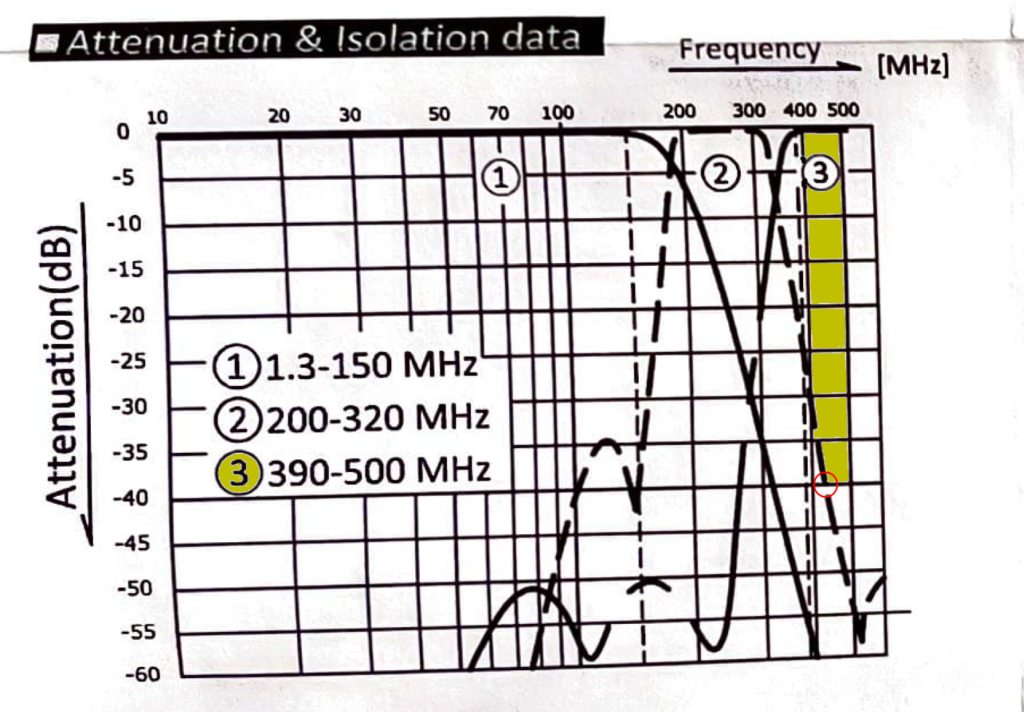
The yellow shaded area is actually 400MHz to 500MHz for simplicity of the illustration and stops when we have at least 40dB of attenuation. We can see Port 2’s bandpass filter attenuates at a minimum of 40dB right at or around 420Mhz. There is adequate attenuation protecting Port 2 from that RF power, indicated by a red circle in the graph above.
It is safe to say that I will have at least 40dB of RF attenuation in Ports 1 and 2 from Port 3. No significant RF power from the 70-cm rig will reach the other 2 ports.
Bandwidth
Each port offers the appropriate bandwidth for each of the 3 bands out to the antenna. Port 1’s bandwidth is between 1.3MHz and 150MHz, Port 2’s bandwidth is from 200MHz to 320MHz, and Port 3’s bandwidth is from 390MHz to 500MHz.
Connecting it all Together
Since the FT-991A has a single SO-239 connector for 2-meters and 70-cm, I needed a duplexer to be able to connect the FT-991A into the triplexer. Keep in mind the triplexer has 3 ports, and Port 1 is 2-meters, Port 2 is 1.25-meters and Port 3 is 70-cm. I need to connect the single 2-meter/70-cm output from the FT-991A into the 2-meter and 70-cm ports on the triplexer.
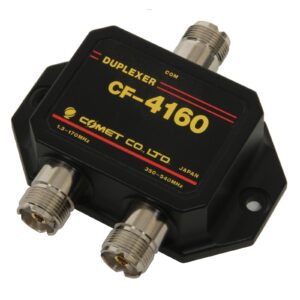
Comet makes a duplexer, the CF-4160 which would allow for 2-meter and 70-cm inputs to a single output or common.

The CF-4160 duplexer attenuation graph is much easier to follow. This duplexer sufficiently isolates the two ports (2-meter and 70-cm) and covers the bandwidth necessary for each band.
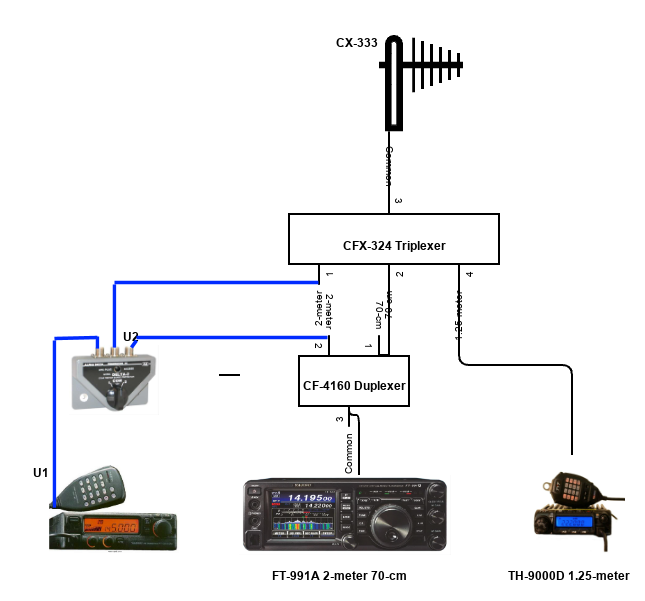
I connected the common to the FT-991A and then the two other connections (2-meter and 70-cm) from the duplexer to the triplexer (2-meters and 70-cm).
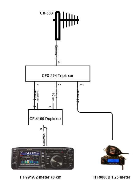
The completed setup can be illustrated as follows:
Note that you can’t simply connect the FT-991A’s single 2-meter / 70-cm antenna connection to the triplexer using a splitter, or to just one of the connections on the triplexer.
Update
Since my original post, I had been using digital modes on HF and needing to be able to use 2-meters at the same time for a chat or to participate in nets. I had an old Yaesu FT-2500M that I could use, so I added an A/B switch between the 2-meter input to the triplexer and the FT-991A and FT-2500M:
Having a diagram helps visualize how to place the switch and to keep track of the connections.
I also used a Dymo label maker to add labels / tags to each coax connection around the switches so that I can easily see which position is for which radio, both for this and the 4-port HF antenna switch.
Final Thoughts
Using the combination of the duplexer and triplexer to connect both the FT-991A and TH-9000D works quite well. Both can receive and transmit at the same time without affecting the other. Since I most often monitor both rigs at the same time, I am able to do so with a single antenna.
The FT-991A shows no sign of RF or interference on the waterfall when transmitting on the TH-9000D and the TH-9000D does not indicate any interference when transmitting from the FT-991A.