
Kenwood TS-830S CW Filter Installation
In older HF rigs, filters were actual circuits with crystals which would pass through a narrow portion of the input signal bandwidth and attenuate anything outside of that range. This is helpful in CW for example, when a 2400 – 3000 Hz bandwidth may have several stations within it all transmitting CW at the same time (think FT8 and the waterfall view). How easy is it for you to hone in on just one of those stations and decode or copy? Sure, it can be done, but it can be much easier if all of the adjacent stations were muted.
Modern rigs have DSPs which can perform similar functions in software instead of hardware. Almost all modern rigs have a CW filter mode, and many even allow you to adjust how narrow that mode is.
I have two Kenwood hybrid rigs which do not have DSPs or touch screens. All of the filtering and audio is done with hardware or circuits. Because not every operator who purchased one of these rigs would use it for CW (and to keep costs down for the consumer), these rigs weren’t always sold with the CW filters installed. These are often optional accessories that can be purchased and installed separately.
I recently purchased a TS-830S from eBay and was hoping it had both optional CW filters installed. However, I discovered that it did not have them installed.
Filter Options
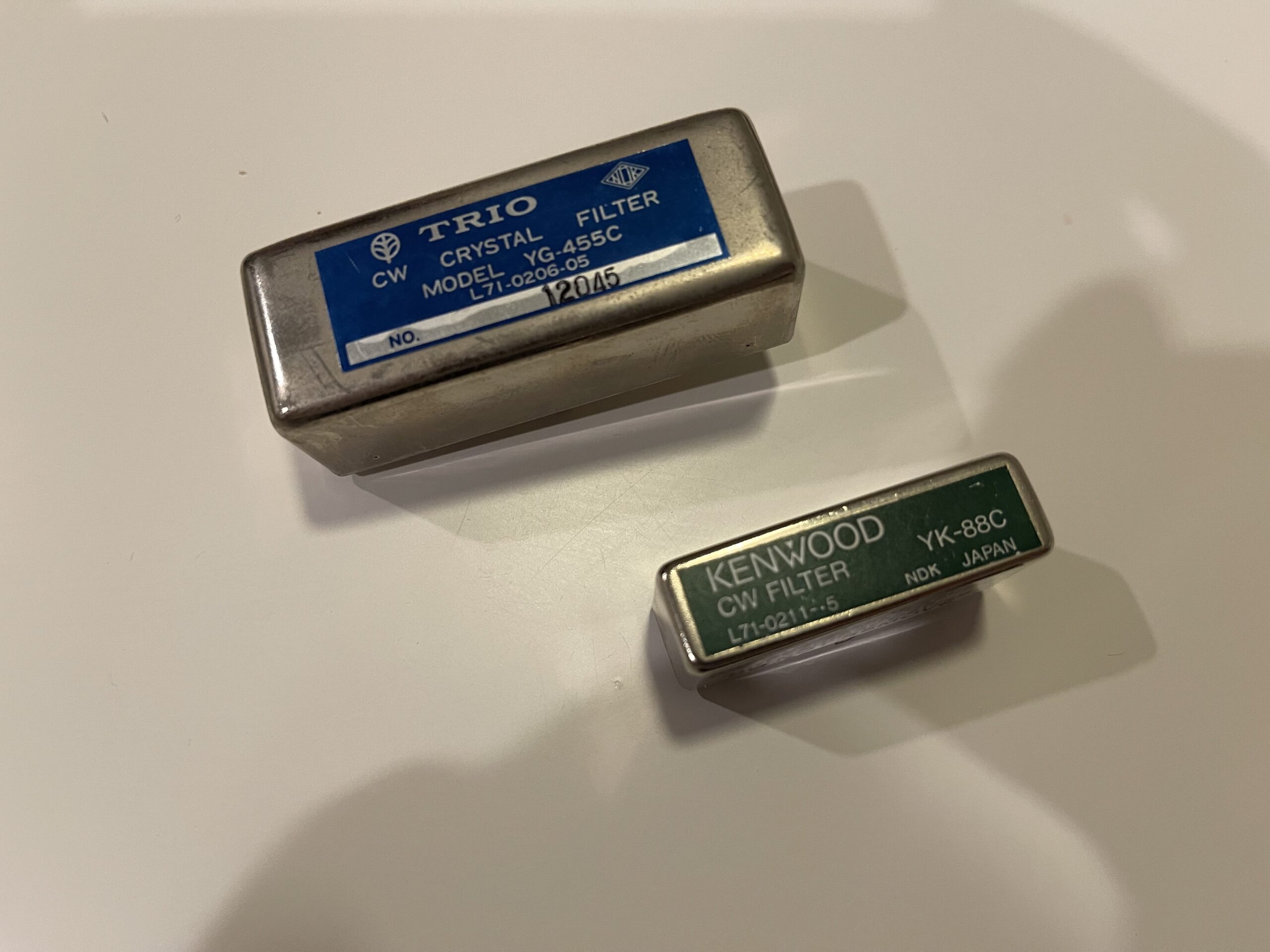
Since my TS-530SP has the optional YK-88C CW filter installed and I have used it quite a bit recently, I decided to seek out the optional CW filters for the TS-830S.
Since the TS-830S has variable bandwidth tuning (via the VBT control), without any optional filters, it is possible to narrow the IF bandwidth down to as little as 500 Hz. With the YK-88C and YG-455C filters installed, you can narrow the IF bandwidth to as little as 150 Hz with the VBT control.
The owners manual describes the process to install the filters as well as the various filter combinations available. There are very narrow filters (250 Hz or 270 Hz) and narrow filters (500 Hz). The recommended combination is the YK-88C with the YG-455C. Using both filters allows for a more complete VBT control.
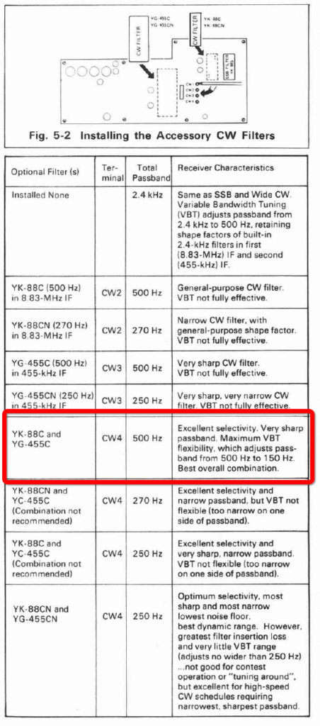
The selected combination above was what I sought out to install. This combination is recommended by Kenwood as opposed to the other combinations as it gives the most flexibility (500 Hz – 150 Hz).
If you do not want or need both filters, the chart above indicates that you can use just one filter, the YK-88C 500 Hz filter in the 8.83 MHz IF slot, and the corresponding jumper would be CW2 for this configuration.
Sourcing the Filters
Sourcing these filters is not inexpensive. You can salvage them from another rig that had them installed, find them on eBay, hamfests, or other sources. Of course, due to the age of these rigs, the filters you find will not likely be new. I have heard that these filters can degrade or their characteristics can change with age. Many will recommend doing a “sweep” on them before installing them to make sure they are up to spec. However, a function generator and scope might not be readily available to you. In my case, I do not currently own a function generator nor a Nano VNA. I chose to install the ones I sourced without testing them beforehand.
Inrad makes filters for Kenwood HF radios, they have a 400 Hz pair of CW filters that would work. However, these too aren’t inexpensive. I suppose if you are unable to find the original Trio/Kenwood filters, the Inrad filters would work just fine.
Installation
The owners manual describes the installation process in detail. The filters are installed on the IF board, and their locations are clearly marked on the PCB and in the owners manual.
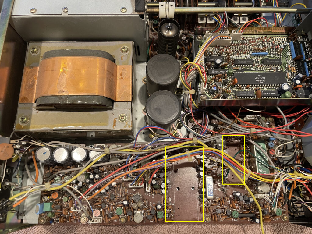
There are 8 screws along the perimeter of the IF PCB, and the IF PCB has many molex type connectors. I removed all 8 screws and left all of the connections to the PCB intact. I did not have the confidence to unplug any of these molex style connectors, as I did not want to flex the board at all, nor risk breaking any of them. Instead, I decided to swing the board up from the outer edge just enough to reach the connection points needing to be soldered.
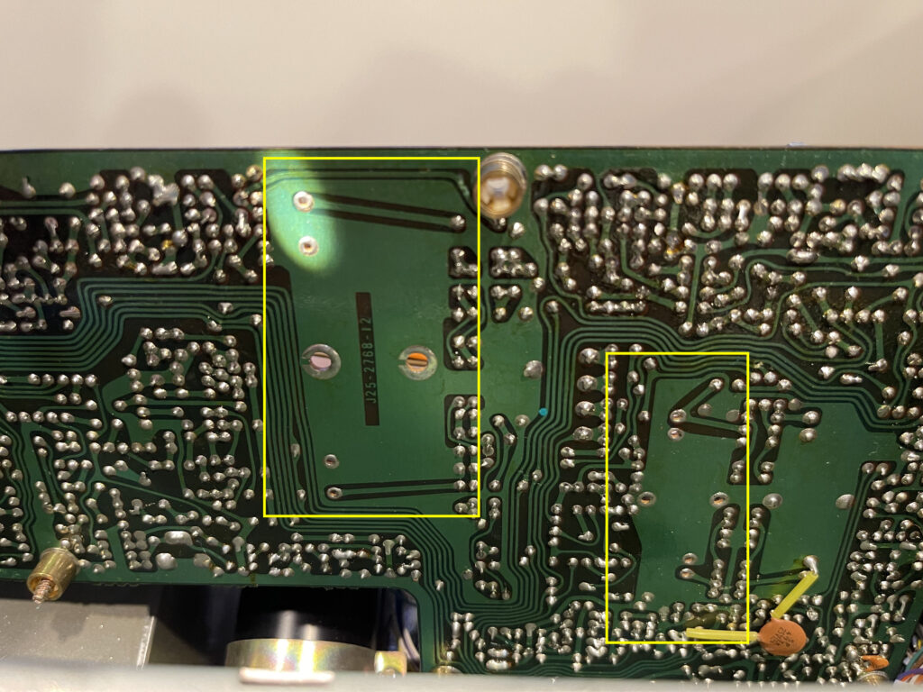
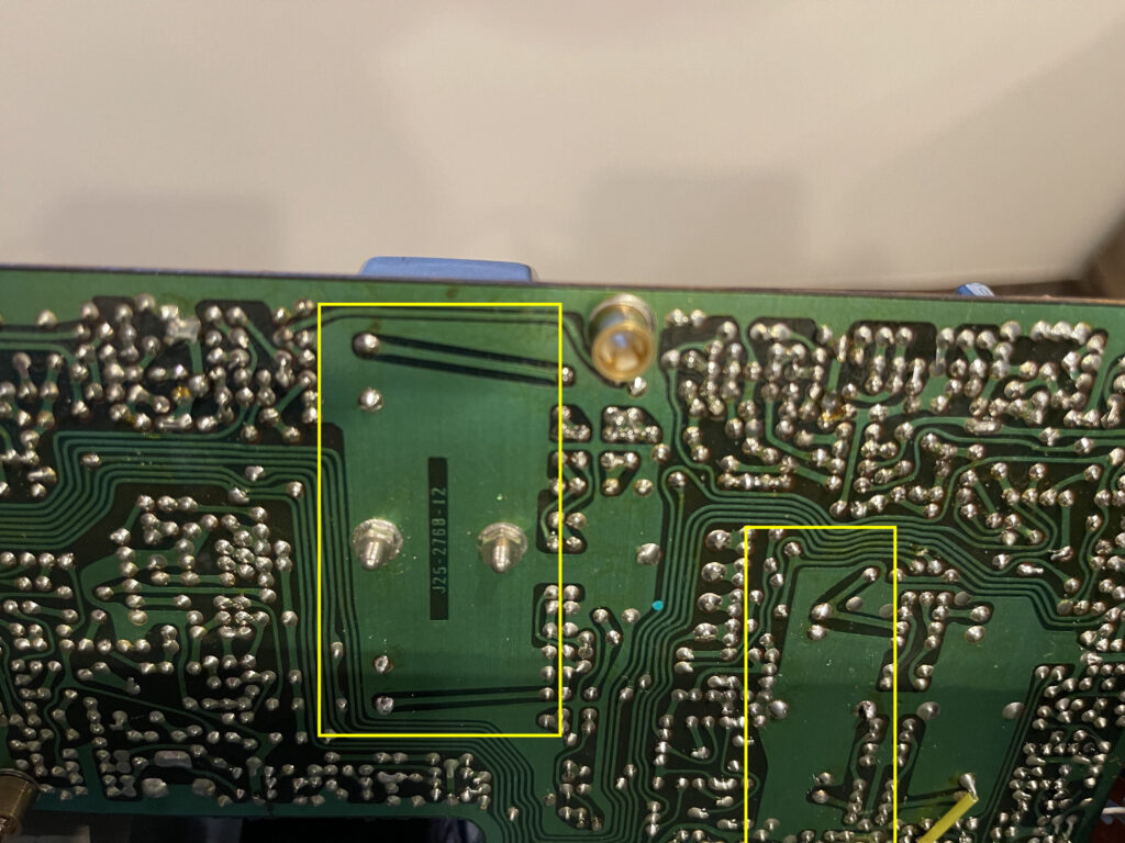
There was just enough room to solder the connections needed after swinging the board up slightly.
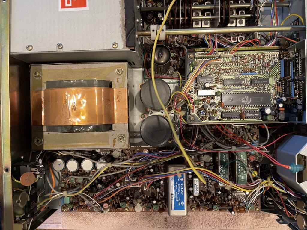
I placed the IF PCB back into its original position and the 8 screws back into place. The IF PCB has 4 points for the jumper position for the filter options. These are labelled CW1 through CW4, and the chart in the owners manual indicates which position the jumper needs to be in based on the installed filters. In this case, CW4 was the correct position.
I powered up the radio, and verified the filters are working and audio is passed through as expected. I suppose if the filters were not installed completely, or the jumper was in the wrong position, there would either be no audio when in narrow CW mode or greatly reduced or distorted audio in the narrow CW mode if the filters were bad.
The installation was successful, and it was much easier than I had anticipated. I was hoping to not have to remove the IF PCB completely, and I was able to install the filters by swinging the board up a bit from the chassis.