
Kenwood TS-830S HV Caps Replacement
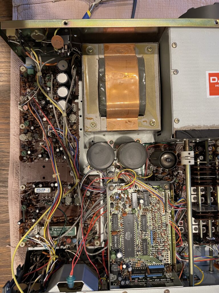
A few days after I got the TS-830S on the air, I began to tune up for 10 meters and was having difficulty peaking the RF output after dipping the plate. Increasing the load control didn’t seem to increase forward power output at all. Then I noticed output power dropping a few seconds after flipping the switch to “send”.
At this point I was thinking either HV caps were starting to fail or perhaps the driver tube was wearing and this is usually most noticeable on 10 meters. I tried to tune up on 40 meters, and had the same results.
Low HV Voltage
I decided to check the HV reading on the meter and it was just above 400 volts. It should be around 900 volts. I ordered an HV repair kit from K4EAA, and just a few days later, my parts had arrived.
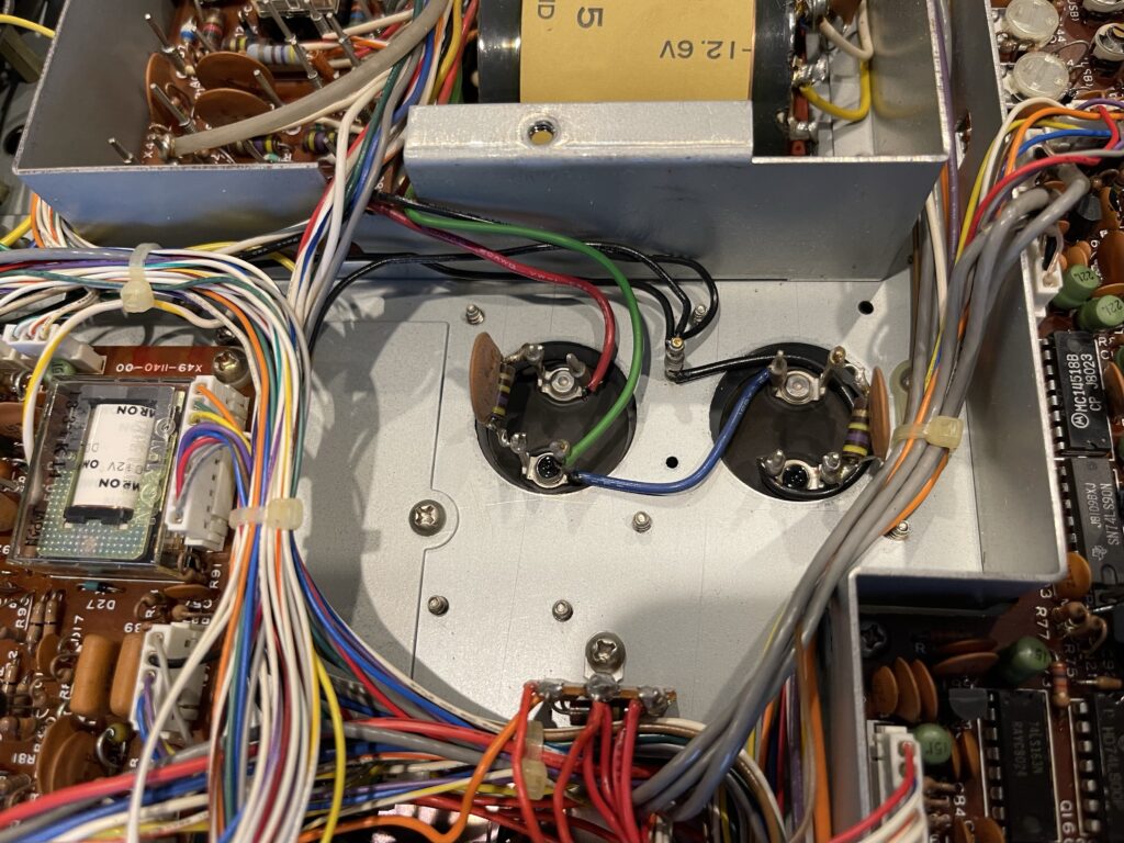
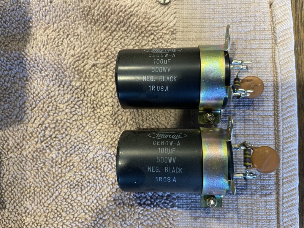
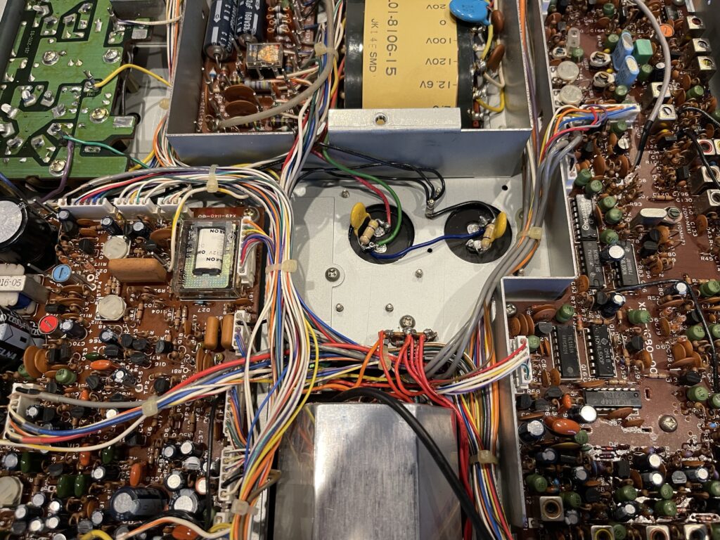
The replacement caps are less than 1/2 the height of the originals and much lighter. Thankfully, the replacements are the same diameter, so they fit within the original mounting brackets. The replacements also had a clear plastic sticker placed over the tops so that accidental touching of the top side of the caps with the power on would not cause a shock.
The reason for this concern is there are 2 capacitors in series. Across them is about 850 volts. This means if I were to accidentally touch the top of one of them, that might be the one with about a 400 volt potential difference to ground. The original capacitors were encased in plastic, including the tops. Just in case there were for some reason a low resistance to one of the terminals via the case of the capacitor, it’s best to assume it’s hot.
Capacitor Discharge
The caps in the TS-530SP and TS-830S have a self discharge resistor across the terminals so that the voltage is bled off shortly after power down. The bleed off takes a minute or so, and it’s best practice to discharge these caps anyhow as a precaution. Usually for caps this size, a 2k-20k ohm resistor rated at 2-5 watts is sufficient as a bleed off tool.
It’s best not to simply short a capacitor to discharge it. You could very well exceed the current limit for the capacitor and either shorten the life of the component or completely destroy it.
I built a discharge tool using several resistors in parallel (I didn’t have any 5 watt resistors on hand) and used alligator clips on both ends. As a precaution, I discharge the HV caps by clipping on the discharge tool to both terminals of each cap, one at a time. I’ll wait a few seconds and then verify zero voltage with my DVM. If you’re curious to see how quickly the caps are bled off after power off, carefully connect a DVM to the terminals of the cap (DC in this case), power down and unplug the rig while watching the meter. Be careful doing this! There is at least 800 volts on both caps in series. Do not take the covers off the radio while plugged in or when powered up unless you have experience with older electronics. High voltages exist within the radio, at various points.
The reason for this precaution is equipment this old could have bleeder resistors which have become “open” resulting in effectively no bleed off. Or, perhaps the bleed off is slower than expected and high voltages could still be present.
There’s a reason why the General and/or Extra class license prep and question pools have content on the subject of potentially high voltages on antennas and inside radio equipment. All of this content becomes quite applicable when working on projects like this.
I recall some content on the amateur Extra class exam regarding discharge time of caps, which varies with voltage, farads, and resistance involved. That content is also quite relevant in this case.
Testing Old Caps
I decided to test the old caps after they were removed to see how close my DVM is in measuring capacitors. After all, it is a very inexpensive DVM and the fact that it claims to be able to test capacitance is a bonus.
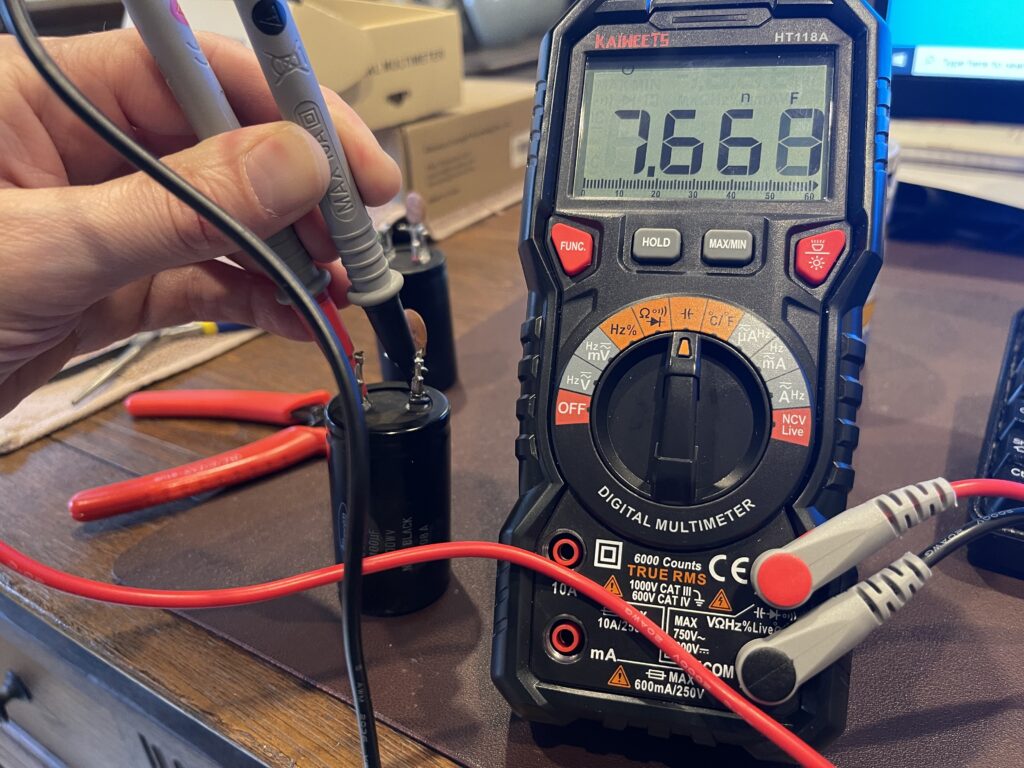

In order to test these, I clipped one lead of the bleeder circuit off so that the capacitor had no load across it and no capacitance in parallel with it. The capacitors are labelled as 100 micro farads. One of the capacitors tested at 7.67 nano farads and the other at 122.3 micro farads.
Smoke Test
I replaced the HV caps in the TS-530SP a few months prior, so this was identical. I was careful to verify the polarity of each cap and verify the wiring after I was done and before powering up the rig.
The only difficulty was wiring up the bleeder circuit and rig connections with just the single posts on each capacitor. The originals had 2 posts per lead, making it easier to connect to the rig while at the same time connecting a bleeder circuit across the terminals.
The kit from K4EAA included both the resistors and caps for the bleeder circuit so that I did not have to salvage the old ones.
I powered up the rig, performed the tune up process and verified the HV voltage on the meter at a little over 850 volts. I’m hoping this will be the last maintenance item for awhile with this rig and this was a rather simple job to complete.