
TRS-80 Model 100
I recently opened up a box where I had kept my old calculators (TI and Radio Shack) and I recently restored a Sharp CE-150 printer cassette interface for the PC-1500 / PC-2. I had been searching eBay for plotter parts and kept seeing postings for the TRS-80 Model 100.
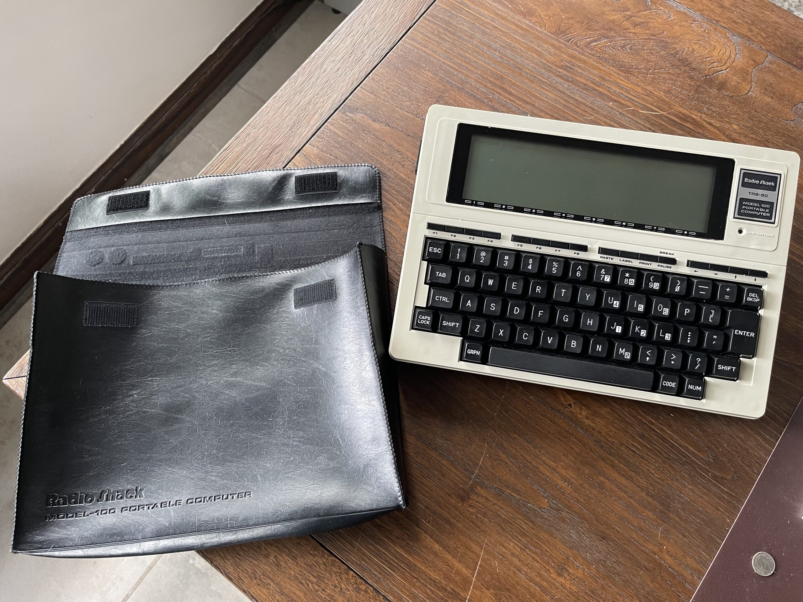
I remember seeing this portable computer in the Radio Shack catalogs back in the 80’s. I had never seen one in person, but I do remember they were seemingly around for awhile, and seeing them abundantly available on eBay piqued my interest.
Due to the simplicity of the device, it powers on instantly and can be programmed either in BASIC or 8085 assembly to fulfill a specific purpose. I thought this would make a good terminal for a packet TNC, since it has a serial port and built in terminal program that can run between 300 and 19,200 baud. The Model 100 has a multi-line display and a full size keyboard.
The TRS-80 Model 100 runs on 4 AA batteries or via a 6 volt DC adapter. On battery power, the Model 100 boasts about 20 hour battery life on 4 AA batteries.
The Model 100 is often referred to as the “Model T” because it was one of the first popular laptop PCs. It was quite successful as Radio Shack allegedly produced about 6 million of these units.
Some of the features of the Model 100 are:
- Up to 32 KB of RAM
- RS-232 port up to 19,200 baud
- Built in 300 baud modem
- Parallel printer port
- Buzzer for sound
- Multi-line dot addressable LCD
- Full size keyboard
- Up to 20 hours on 4 AA batteries
- Built in terminal program and text editor
- BASIC and 8085 assembly for programming
- Cassette interface
- RAM backup with internal rechargeable battery to prevent program and data loss
- ROM slot for adding custom or commercial ROMs.
Sourcing from eBay
I searched through a few postings on eBay for a Model 100. There is quite a difference in price between postings. Some had all of the accessories included and claimed a fully working unit. Others would have none of the accessories and note “parts only” or repair.
I was interested in a working unit and one which had the accessories. Specifically the soft case, parallel port cable, AC adapter, and owners manual. I was careful to inspect the photos for leaking AA battery damage, screen damage and general appearance. I was interested in the Model 100, not the Model 102 or the successors.
I was lucky to find a Model 100 24 KB version with all of the accessories and a carry case. The condition was excellent and it did in fact work when I put batteries in it.
Typical Issues with Age
As with most vintage electronics, there are some components which do not survive the test of time. For example, internal battery packs and electrolytic capacitors can leak over time. In the case of the Model 100, the internal RAM backup battery is NiCd and is known to leak. When it does, it can cause quite a bit of damage to the PCB and/or nearby components. When electrolytic capacitors leak, they can fail open or short, damaging other components or cause erratic operation.
Sometimes AA batteries are left inside the unit and those too will eventually leak.
Initial Assessment
My unit had a NiCd pack that had just started to leak, but not yet reached the PCB. It had some minor corrosion in the AA battery compartment. For the time being, I removed the NiCd backup battery.

Upon further inspection, I noticed many of the electrolytic capacitors had leaked and needed to be replaced.


As with any vintage gear, a decision on whether to proceed with a repair is based on nostalgic value of the item and cost and effort to repair. After all, we really never know how much effort will be needed. For example, replacing a single part might be all that is needed to bring something back to working order. On the other hand, it could be several parts and hours of troubleshooting.
I decided to replace the electrolytic capacitors and then evaluate from there. Since the parts cost was under $20 with shipping, it wasn’t an expensive attempt to undergo.
Sourcing the Parts
I ordered replacement capacitors from Mouser Electronics and was fortunate to have an excellent guide prepared by Jeff Birt for the replacement part numbers. This made it easy for me to not have to measure the lead spacing and verify sizes.
Some of these capacitors were non polarized. The schematics and parts list in the Model 100 service manual were helpful in verifying the correct replacement parts.
Two of the capacitors on Jeff’s list were not currently available from Mouser, so I substituted similar ones. Note that non polarized capacitors will work where a polarized capacitor was, but not the reverse. If you can find only a non polarized equivalent, it can be used in place of the polarized capacitor. It is simply a bit more expensive than the non polarized option.
Experience Needed or Gained
Recapping a PCB can be challenging if you do not have experience. I had never done this before, but I did have soldering experience. The challenge here is to be able to remove the old capacitor without damaging traces or the PCB. This requires the right balance of heat and technique for extraction.
At first I struggled to remove the first few caps. This was because I was using the wrong soldering tip. The tip I was using was the one I use to solder small components onto small PCBs. The heat from the iron was not transferred efficiently to the pads where the capacitor was soldered into. Adding more heat (raising the temperature on the iron) did not really help. The result ended up being that while the solder was melted on the pad, it was not enough transfer of heat to run through the component lead to the other side of the board.
I changed the soldering iron tip to a small wedge style tip, which immediately worked to not only melt the solder on the back of the board, the heat instantly transferred all the way through the component lead to the other side of the board.
For the capacitors which had narrow lead spacing, I was able to use the wedge tip to heat both leads at the same time while gently pulling on the capacitor from the other side of the PCB. The end result was a few seconds with the iron and the cap was removed quickly.
For the capacitors that had greater lead spacing, I simply heated one leg at a time, alternating between the two, rocking the cap back and forth, allowing for incremental raising up of each leg of the cap until it was completely free of the PCB.
After removal of the old capacitor, any remaining solder in the through hole needs to be removed or opened up enough to place the new capacitor in. I ended up finding that solder wick worked very well for this. I do have a desoldering iron, but I decided not to use it. I did not want to risk using too much heat on this PCB and damage traces or pads. My particular desoldering iron does not have a temperature control on it.

Damage from Leaking Capacitors
The electrolyte from the electrolytic capacitors had leaked out of about half of the capacitors on the PCB. When it leaks, it tends to work its way under the solder mask and along the copper traces in the board. Visually you can see dark spots along these traces and between layers of the fiberglass.
I do not have the knowledge or experience to address the damage from the leakage, other than to use 90%+ isopropyl alcohol with a swab and toothbrush and clean the affected area after removing the capacitor.
One thing that was especially important was to be sure the top pad was cleaned enough for solder to adhere to it. When soldering the replacement capacitors in, the solder is applied to the pad on the bottom side of the PCB. The solder needs to make its way through the PCB via the component lead and adhere to the pad on the top side of the PCB.
I’m not certain on the design of this particular PCB in terms of whether the through hole for the component (the “via”) is necessary or part of the connection pathway. For example, if the leaking electrolyte damaged the copper traces or metal plating through the hole, then the solder pathway would be needed between the two pads (on the top and bottom of the PCB) to form the complete electrical pathway. If the top pad is not cleaned properly or if it is damaged from the leaking electrolyte, the solder will not adhere.
Testing
After replacing all of the electrolytic capacitors and verifying the correct polarity (where applicable) and the correct values, I powered up the Model 100 and saw the home menu – success! I felt around the board a bit for sources of heat and found no issues. None of the magic smoke was let out.
I tested the RS-232 port with my windows desktop using PuTTY and had no issues. I do not have a parallel printer currently, so testing that port can wait. I will build a cassette interface cable to test out loading and saving to and from tape.
Final Thoughts
Now that I have recapped and removed the leaky NiCd backup battery, I am going to experiment more with BASIC and 8085 assembly with the Model 100. At some point I will replace the NiCd backup with either a super cap, or an NiMh equivalent. For the time being, I can use the AC adapter while changing the AA batteries to prevent memory loss.


I plan to use the Model 100 with HF & VHF TNCs for Amateur Radio and with the FT5D HT for APRS.
There is a group of Model 100 enthusiasts here, and an organization with files, documentation and more here.
Josh Malone had given a presentation on repairing Model 100’s at Tandy Assembly 2019 and the video can be viewed here.
Updates
Since the recap project of my Model 100, I finally replaced the NiCd memory backup battery with an NiMh battery. I had let my rechargeable AA batteries die down a few times and lost my memory contents (I use the backpack drive to save and load files when needed), but it was annoying to have to reload the backpack bootloader each time my AA batteries died.


The Model 100 has a memory battery On/Off switch on the bottom to preserve the charge (and probably extend the life) of the battery when storing the unit for long periods of time. I tested the backup battery by allowing it to charge up for a few hours with freshly charged AA batteries then took out the AA batteries. I waited a few hours and when I put the AA batteries back in, the memory contents remained!