
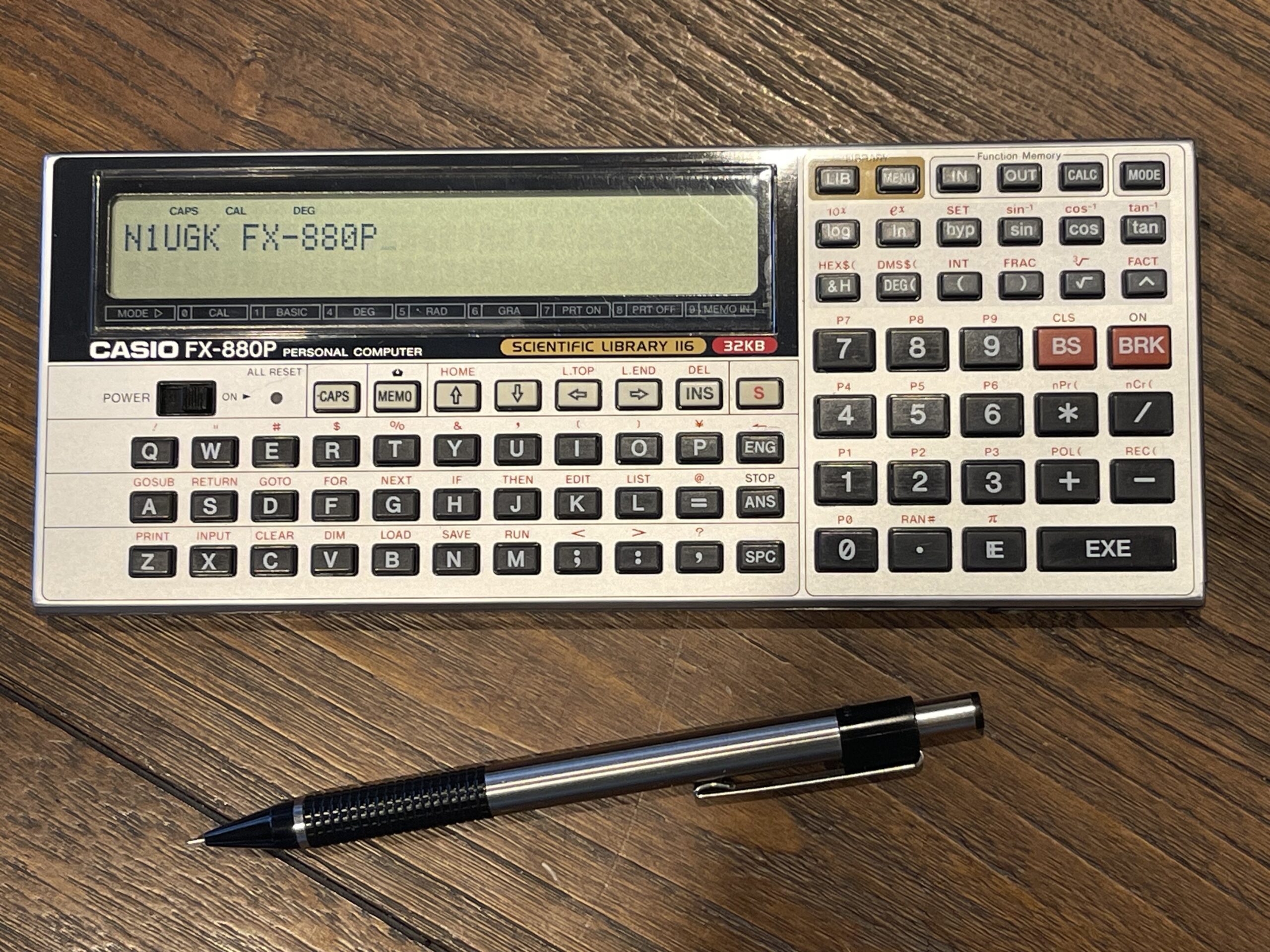
Casio FX-880P Personal Computer
The Casio FX-880P was released in 1991 and was a bit bigger than the PB-100 series, and added a data bank feature and scientific function library. Previous similar models were the FX-860P, the FX-850P among others. Other models which are similar are the VX-4, FX-890P, and the Z-1GR (these models released only in Japan).
The FX-880P (and similar FX-850P) is still widely available (at the time of the writing of this post). I had acquired this model by way of the PB-2000C. I had a saved alert looking for a PB-2000C and a listing came up for auction which had a whole bunch of Casio pocket computers in the offer, with the FX-880P as one of the models included.
As with many of these Casio pocket computers not rebadged by Radio Shack, it is difficult to find where and when these were sold in the United States (if ever). Some models are only sold in Japan for example, such as the VX-4 and Z-1GR. If there is an English owners manual, then chances are the model was sold in the United States.
Below is an advertisement which highlights the FX-850P:

I was able to find another advertisement in 1987 (snippet only) where the FX-850P was selling for $149.95. As a comparison to the Radio Shack models, in 1987 the PC-6 was being sold for $119.95. This model would have been a bit more expensive, although with more memory expansion capability, a much bigger screen, and a better form factor. The PC-6 had a “clamshell” design which often would result in broken hinges. In addition, half of the keys are membrane style keys on the upper half of the unit.
The FX-880P has a similar form factor to the PB-100 series (Tandy PC-4), except this model is a bit bigger.

The contrast wheels are both on the same side (on the right), the power switch is similar on both, and the “all reset” was moved to the front on the FX-880P. The PB-100 had the expansion port on top, while the FX-880P had it on the left side.
The FX-880P came with a hard plastic cover, which was an improvement over the PB-100 which had a soft case. The plastic cover had a listing of all of the error codes on the inside of the cover.


The FX-880P came with a reference card listing all of the functions within the included scientific library. This card would fit inside this cover for portability and protection.
Memory
The FX-880P came with 32 KB of RAM built-in and can accept either an RP-8 or an RP-33 memory expansion pack, which adds another 8KB or 32 KB of RAM respectively, for a total of 64 KB maximum.
The FX-850 had 8 KB of RAM built-in and the FX-860 had 24 KB.

Luckily, reproductions of the RP-33 are available from Jeff Birt. The RP-33 is also used in the PB-2000C, AI-1000, FX-840P, FX-841P, FX-850P, FX-860P, FX-860Pvc, FX-870P, FX-880P, FX-890P, VX-1, VX-2, VX-3, VX-4, Z-1, Z-1GR models.
The RP-8 is the same module used in the Tandy PC-6 and the Casio FX-730P.
Since this model comes with 32 KB as standard, this is plenty of memory for most programs, even if large data tables are needed. Unlike many previous Casio models, in my opinion, the memory expansion is not really necessary for this model.
Keyboard and Display
The keyboard is well designed and sturdy, with hard plastic keys and a full “qwerty” layout. Calculator function keys are readily accessible for quick calculations. Upper case characters are the default mode, and lower case characters are supported via the CAPS button.
The LCD is a 32-character by 2-line display, but it is not dot addressable. Each character is drawn as a 5 x 7 matrix. Custom characters can be defined, but full screen graphics are not possible on this model.
There is a contrast wheel on the right side, which I find far easier to use the wheel than keyboard buttons for contrast.
Casio have provided a full set of ASCII characters as well as some other useful control codes, engineering, math, and graphic and icon characters:

This character code table’s relevance will be explained a bit further in this post. Many of these characters are included for readability of mathematic and engineering symbols used in equations and notations, often used within the scientific library feature of this pocket computer.
Buzzer
This model does have a buzzer, but duration is not controllable (not via BASIC). Pitch is limited to either high or low.
LCD Cover
The plastic over the LCD on the FX-880P I acquired had an odd haze on half of it, as if it was oxidized and the other half of the plastic cover had been protected.


I used Novus plastic polisher on the plastic and it cleared right up.
Expansion Port
The FX-880P has a 30-pin expansion port on the left side. This port looks quite similar to the port on the right side of the Casio PB-1000, AI-1000, and PB-2000C.

Even though the port looks the same as the PB-1000, AI-1000, and PB-2000C, it most definitely has a different pinout. The FA-7 and MD-100 (peripheral expansion interfaces) are not compatible with this model.
Interestingly, this port has serial send and receive pins, at TTL levels. It would be quite easy to add either a serial to USB adapter or a MAX-232 IC to this port to build your own serial cable.
Batteries
The FX-880P uses two CR-2032 button cells as the primary source of power, and a CR-1220 as a memory backup for changing the main batteries. This is a very familiar configuration which was shared among many other Casio models.
After about a month of heavy usage in my experimentation with this model, I have yet to have had to change the batteries.
BASIC Capability
Similar to other Casio models, the program space is segmented into ten slots, P0 – P9. With the 32KB RP-33 installed, there are 54,224 bytes available for user programs. 21,456 bytes are available without any memory expansion installed.
A simple counting program illustrates the speed of this model:
10 X=0
20 PRINT X;CHR$(2);
30 X=X+1:GOTO 20
The PRINT command pauses by default after each PRINT statement. This model uses a semicolon to both suppress the automatic newline afterwards, and the pause, if a semicolon is present on the end of the statement.
It can be used to display multiple items on the same line using one statement if desired. I used the CHR$(2) function to issue a “line top” so that the next PRINT executed in the loop will keep the output to the same line on the LCD (to prevent scrolling).
The BASIC supported for this model includes commands such as DATA, READ, RESTORE for data tables. It supports random number generation, many scientific functions, string manipulation, and character conversion as well as bitwise logic operators.
There is support for reading/writing to and from cassette or RS-232 ports. There is also support to read and write to and from the data bank.
It supports PEEK and POKE for direct memory access. Since PEEK and POKE arguments are 16 bit, the memory map for this model is greater than 64 KB. This means that a single 16 bit address parameter to the PEEK statement is insufficient in order to access address space beyond the first 64KB. The upper 16 bit memory address is set using the DEFSEG command. PEEK and POKE arguments are merely an offset from the DEFSEG base address:
actual address = (segment address * 16) + offset addressScientific Library
One of the most interesting features of the FX-880P is the scientific library. It boasts 116 scientific functions or programs. To activate a program from the library, you enter the corresponding function code (4 digits) then press the LIB key.
There was a reference card which came with the pocket computer which lists each of these scientific functions in the library and the corresponding number. The programs are also listed in the user guide.
Also mentioned in the user guide is that these functions are built in BASIC. This means, in theory, you can dump the ROM to the serial port, then convert the tokenized BASIC data to text and see how they were written.
The value of this library being included as a feature in this model is that these scientific and engineering functions, along with the constants, are readily available and do not consume any of the user memory space. Further, one does not need to program these themselves (but can quite easily be accomplished if needed). It is like having a software package being included with the pocket computer for free and being preloaded – and not being erased when changing the batteries.
For historic reference, Radio Shack sold software packages (including math and engineering packages for example) for the PC-1 and PC-2. These were distributed on cassette and would be loaded into the pocket computer, taking up user program space.
Owners Manual and Service Manual
The owners manual for the FX-880P is linked below:
The service manual for the FX-850 (similar) is linked below:
Peripherals
The FX-880P can be connected to various peripherals, many of which can be used with several other pocket computers. The FX-880P uses the FA-6 interface box in order to connect to printers, cassette recorders, and RS-232 devices.

Casio offered two printers which could be connected to the FA-6 (and other expansion interfaces) for other pocket computers. One of those printers is the Casio FP-40, a thermal printer. It has two modes of operation, a 40 character mode and an 80 character mode. It has multiple character tables for various regions with dip switches to select the character table. This is a nice feature because it does not require swapping ROMs for changing the character table, or ensuring you have the correct version for your region or language.

The FP-40 also allows for bitmap printing, which provides for graphics and characters to be printed which are not part of the character tables. The printer uses 112mm thermal paper which is still available today.
The printer has a generic 40 pin connector which allows adapters (interface packs) to be plugged into the printer for connection to various types of pocket computer bus connectors.
For the FX-880P, the SB-44 adapter would be needed for a direct connection to the FX-880P. To use this printer with the FA-6 or any standard Centronics connection, the SB-43 would be needed. There were also adapters available for the FX-7xx and FX-8xx pocket computers (like the Radio Shack PC-5 and PC-6), PB-100 (Radio Shack PC-4), and others which had the single row 12-pin bus connector (the SB-2 cable was also used with these models).


The FP-40 printer also has a cassette interface for loading and saving programs. This allows for a complete solution (minus the RS-232 capability) as an alternative to the FA-6 interface box.
The SB-43 adapter would allow the FP-40 to be connected via a standard 36-pin Centronics cable. This would be useful for the FA-7 or MD-100 for the PB-1000, AI-1000, or PB-2000C.
This printer is commonly found today, but the adapter modules are a rare find. It would not be too difficult to build an adapter, since the printer itself has a standard port connector which can be found today. The challenge however would be finding the connectors for the other side of the adapter, or the side that plugs into the pocket computer(s). If I find a bargain on an FP-40, I would build an interface for Centronics connections.
The other printer Casio offered which could be used with the FX-880P is the FP-100. Unlike the FP-40, this printer has only a Centronics connection option, which would require the FA-6 interface box in order to use it with the FX-880P. The FP-100 is a 4-color full page plotter, which I happen to have. It uses a variant of the Alps plotter mechanism similar to other printers of its type, except that the pens are vertically oriented.
The pens are the same as Alps models found in the smaller pocket computer printers, Atari, Commodore, Radio Shack, and others. Luckily I have found a way to refill these pens when needed. This plotter is quite useful as it has a standard Centronics connection which allows it to be used for the PC-1500 (Radio Shack PC-2), the PB-1000, PB-2000C, AI-1000, the FX-880P (and similar models), and even a PC.
In researching the FX-880P, I found a reference to the MD-120, which was a 3.5” floppy disk drive. It requires the SB-5 cable to connect between the pocket computer and the disk drive. I have not been able to verify this as I could not find any user manuals online.
Casio FA-6 Interface Box
The Casio FA-6 is the interface box for this model which provides not only the cassette interface but a serial RS-232 port and a parallel port (Centronics).

The FA-6 connects to the pocket computer via the expansion port on the left side of the FX-880P.

This connection style is a departure from the typical docking station type of interface box, but it allows a more flexible placement of the box and pocket computer.

Thankfully, the FA-6 does not have any internal NiCd battery pack which could leak and damage the interface like other previous expansion boxes often suffered damage from. The FA-6 uses 4 standard “AA” size batteries.
The FA-6 allows for connection to printers and modems for example. The Casio FP-100 or FP-40 printer can be attached. Alternatively, most parallel (Centronics) printers can be used, provided they have a character mode for basic character printing, otherwise any special printer commands would need to be performed within your BASIC program.
A serial printer could also be attached, but would not have built-in BASIC support for printing (via LPRINT); custom output would need to be performed within your BASIC program, much like I performed while experimenting with the TP-10 thermal printer, which had a serial connection.
The FA-6 I acquired came with no connection cables whatsoever. This is similar to the FP-40 printer which had connection options which were to be purchased separately.

Only the RS-232 (serial) port connection is standard or commonly found today. The cassette interface (MT) is an 8-pin DIN style connection, and the parallel port is a 14-pin mini Centronics connector.
Since I have several options to attach a printer to the FX-880P, a banner program can be written for this model. I could also write a maze program, but its output would need to be written to the printer, skipping the output to the screen.
Further, I could dump the memory and ROM to the RS-232 port for inspection and experimentation.
However, in order to make use of the FA-6 for printing and/or using the cassette interface, I would need to build a few cables.
The FA-6 owners manual is linked below:
Custom Centronics Cable Needed
The FA-6 parallel port connector is not the standard 25-pin connector usually found on an older PC, or the 36-pin Centronics connection found on the Casio MD-100 or FA-7. Therefore, a standard Centronics cable will not work with the FA-6 interface box.
Casio had offered the PK-7 cable, which has the smaller 14-pin Centronics connector on one end with the standard 36-pin Centronics connector on the other end.

Needless to say, these are not commonly found today, and if they were, they would likely be rather expensive.
I was able to find this smaller male Centronics connector (two of them) on eBay, for around $14 with shipping. The other standard sized Centronics connector can be found on Amazon, or, you can buy an inexpensive cable which has this connection on one end.
I bought a cable on Amazon which had two 36-pin Centronics connectors, one on each end. If I cut the cable in half, I could build two interface cables, since I have two of the smaller 14-pin Centronics connectors I purchased on eBay.
Wiring up the cable for the smaller to larger Centronics connections was rather simple and straightforward. A schematic was available for both the Centronics connection and the MT (tape) connections on the FA-6:

The pinout for a standard 36-pin Centronics port is below:

When looking at the 36-pin Centronics pinout, many of the pins are ground. The actual pins needed for communication (printer perspective) would be the 8 input data lines and strobe input. The output would be the printer busy pin and there is also a signal ground.
In my searches for verifying which pins were needed and double checking my guess work, I discovered that the MSX computer standard often included a parallel port with the 14-pin Centronics connector on it.
Suddenly it made sense as to why Casio also used the 14-pin variant. Not only did it save space compared to the 36-pin connector, it had been somewhat common on the MSX and perhaps other systems as well.
Several manufacturers made adapter cables between the 14 and 36 pin standards, and I found a document which outlined the pinout or wiring between the two types of connectors:
I used the wiring diagram outlined above, which was interestingly a 1:1 match pin-for-pin. This was quite a simple conversion to wire up.
The connectors I had purchased had the pin numbers etched into the connectors. This made the process of mapping out the connections quite simple.


I tried a new method of protecting the unused wires in my connection from shorting or coming into contact with each other or other pins. I put a small dab of super glue on the tips of each cut wire so that it would be somewhat insulated and prevent electrical contact with other wires and pins.
I assembled the cable and gave it a go, and it worked! I have rarely built a cable correctly the first time.
Cassette Interface
The FA-6 has an 8-pin DIN style connector for the cassette interface. The Casio SB-7 cable is what is intended to connect a standard tape recorder to the FA-6.
8-pin DIN connectors or cables can be found on Amazon, and I usually buy them as cables with connectors on each end. I then cut the cable in the middle, which provides for two connectors with some cable for connections.
I also had spare 1/8” (3.5mm) and 3/32” (2.5mm) cables for the cassette connections. This was a relatively straight-forward cable to make.

Using the schematic referenced in a previous section, the pinout was:
| Pins | Description |
| 2,4 | Audio Output (TX data) – Headphone |
| 2,5 | Audio Input (RX data) – Microphone |
| 6,7 | Remote |
This cable also worked on my first wiring attempt, surprisingly.
Loading and Saving Programs via RS-232
Saving and loading programs using the RS-232 port is far more convenient than using the cassette interface. Even when using a computer to capture and save the audio stream, getting the levels and settings correct for a reliable transfer is a skill.
The FX-880P can save a BASIC program to the RS-232 port using the following command as an example:
SAVE "COM0:6,N,8,1,N,N,N,N,N"This saves the selected program at 4800 baud, 8, N, 1, no flow control to the attached device, in my case, a PC. I used CoolTerm to capture the received data to a file.
Note that the data sent over the wire is ASCII, with the line terminator as CRLF (&H0D &H0A). This is really convenient for readability and you can also write a program in notepad for example, and send it to the pocket computer with no translation or conversion needed (unless special characters are used which do not map to the same value between the two systems).

The corresponding load command would be:
LOAD "COM0:6,N,8,1,N,N,N,N,N"It should be noted, as with all other pocket computers, the BASIC program is not stored the same way in memory: it is tokenized. This model does not have a specifier for ASCII versus binary when transferring programs as the PC-2 did. Only ASCII transfers are supported via the LOAD and SAVE commands.
When sending BASIC files to the pocket computer, it is best to add a delay after each LF character sent, so that the pocket computer has time to convert and tokenize the line before sending the next line. CoolTerm has a setting to accomplish this.
Further, I have not found a way to terminate the program in such a way that the load screen quits on the FX-880P. After the transfer completes, I simply wait a few seconds, then press the BRK key, and find that the program has been loaded successfully.
The baud rates supported by the FA-6 RS-232 connection are 150, 300, 600, 1200, 2400, and 4800 baud. I have had no issues with 4800 baud for sending and receiving on the serial port.
Dumping Memory to Files via RS-232
Because the FX-880P supports PEEK and POKE, discovering undocumented features and direct memory access are possible. I wrote a small program to dump any segment of memory to the serial port:
10 CLEAR
20 OPEN "COM0:6,N,8,1,N,N,N,N,N" AS #1
30 D = 0
40 DEFSEG = D * 4096
50 B = PEEK(A) : PRINT #1, CHR$(B);
60 A = A + 1 : IF A <= 65535 THEN GOTO 50
70 CLOSE
The program above opens a connection to the RS-232 port at 4800 baud, 8, N, 1, no flow control. As written above, the first segment of 64 KB is output. Changing the value of D on line 30 to values from 0 to 15 would include all possible segments of 64 KB within the memory map. Lastly, line 50 has CHR$(B) as the output being written to the serial port, which outputs the byte value of B directly to the serial port as it appears in memory.
I started with a hard-reset (all reset) on the FX-880P, then a NEW ALL command, then loaded the program above into position P0.
I ran the program for all segments (0 to 15) and saved each to file(s) to my PC. I then reviewed those files directly and much easier than inspecting memory on the pocket computer itself. These dump files are useful for inspecting what is stored in memory and how it is stored. Below are my observations on what each segment is:
segment0.bin - RAM (32 KB built-in and optional 32 KB expansion)
segment1/2/3.bin - No content
segment4.bin - first half of scientific library ROM
segment5.bin - second half of scientific library ROM
Segments 6 through 15 appeared to have no content, similar to segments 1 through 3 (all &HFF). Note that I had the RP-33 memory expansion module installed.
After dumping the memory to a series of files on the PC, I noticed much of the memory space appeared to have BASIC routines within the ROM space (segments 4 and 5). This can easily be spotted due to literal strings being stored as-is (mostly mapping to the ASCII standard), without the need for detokenizing:

I also noticed the first segment (segment 0) contained the display buffer at the very beginning, and user programs appeared in this first segment as well. In fact, I spotted the very program that was dumping the memory to the RS-232 port:

I attempted to run the captured memory files on my PC through Marcus von Cube’s LIST850 program, which claims to be able to read the FX-850P programs and convert them to ASCII (detokenize). I have successfully used these utilities in the past with other pocket computer models without such issues.
I assume the FX-850P uses the same internal tokenization format as the FX-880P. However, the LIST850 program was unable to parse and would throw an error when it hit the &H30 (“=”) character within a BASIC program.
The command line I used was:
list850 -b1234 -n -lF Segment0.txtThe -b switch instructs LIST850 that this is a binary file (not a WAV file), and -n indicates there is no header (this binary file was not captured using the SAVE command). “1234” is an example of the offset, instructing LIST850 where to start. I used the address for where I saw my program begin, and adjusted it back and forward a bit to see if it made a difference.
Invalid data @2D3D \3D - Invalid subtype in data segment.I was really curious about the scientific library in ROM, and the BASIC routines that comprised them. I was hoping LIST850 would be able to parse them. Without any documentation on the internal tokenization format for the FX-880P, I started writing a “detokenizer” program myself.
I viewed my first memory dump to file, segment 0 (DEFSEG=0), searched for “COM0:” and found line 20 from the beginning of my program:

I knew very little about how Casio stored BASIC programs in memory, but I do remember seeing (in previous models I have experimented with) the line numbers are stored using two bytes, in reverse – higher order byte and lower order byte. In this example, my second line number was 20, and it is stored as &H14 &H00. I also knew that Casio ended each line of BASIC with &H00.
My assumption is that the tokens for BASIC commands and functions are two bytes each, and in this case, the OPEN statement would follow the space &H20, with a value of &H04 &H97. Note that some pocket computers (the earlier models) used a single byte for the BASIC tokens.
My second line in the program, including the &H00 at the end is 37 bytes, which is &H25, which we can see right before the line number (&H14 &H00). My guess is that is the count of bytes in the BASIC line. The count byte at the beginning and the terminator byte at the end are highlighted in the image above.
If I were to parse the BASIC statements in any given memory dump file, I can start by examining each byte sequentially, starting at the beginning of the file, and for each byte, assume it is the count byte (value is x) for the start of a line. I can then look forward (x bytes) and expect to see a zero value. If I do not see a zero value, then that byte inspected was not the start of a valid line.
I started developing a detokenizer program which would take an input file (one of the memory dumps saved on the PC) in binary format, and scan it for lines of BASIC using the logic above, and output the result in ASCII as BASIC source code. In order to improve the program, I would need to be sure to run it through for all possible BASIC tokens one might encounter in a program.
I wrote a BASIC program which had every function in it and every operator possible (from the owners manual) and I ran it through the detokenizer program in order to reverse engineer each known token. I found that there were “groups” of BASIC tokens, the first byte (the group) could be &H02, &H04, &H05, &H06, &H07, while the second byte in the token varied (one of 256 possible values). Of course not all 256 values in all groups are valid, otherwise there would be thousands of BASIC commands available for use.
Unknown BASIC Tokens
Once I completed the baseline detokenizer, I ran the two segments of ROM through it (segment4.bin and segment5.bin), in hopes of decoding the 116 scientific functions in the library. I did not get too far into the ROM when I hit an unknown token at position &H09CD:

This token was in group 4 (first byte in the token was &H04) and the second byte was &H76. In order to document what this function was, I POKEd an &H04 &H76 into a BASIC program in one of the user program areas and then LISTed the result:


This undocumented BASIC token was “DEF”, as displayed by the FX-880P. I added this definition to the detokenizer program and the resulting program listing for this particular line of BASIC was DEF CHR$(&HFF)=”FFFFFFFFFF”. Looking at the detokenized BASIC source, this function can define any one of the four reserved characters in the character map, &HFC through &HFF. The parameter is one of the four characters at the end of the character map, and a bit pattern in hexadecimal format with 5 bytes total:
DEF CHR$(&HFF) = "FFFFFFFFFF"One can then display the custom character using:
PRINT CHR$(&HFF)As I ran the rest of the ROM through the detokenizer program, for any unknown tokens found, I would POKE them into my program space and LIST to see the command or function, and then add that definition to the detokenizer program.
Another undocumented token I ran into was CALCJMP (token value &H04 &H9F) in segment5.bin, which was in a BASIC function:

It would appear that you can jump to the formula calculation feature from within BASIC. Further, you can define the formula using the CALC$ variable name and then jump to solve it:

Another undocumented feature would be the ability to jump to one of the 116 scientific library functions from within a BASIC program:

The format appears to be LIB0: which specifies the library is the destination of the jump and then the prefix and function number. There is a mapping table at the end of the segment5.bin which is outlined further below.
The library functions starting with the prefix “S” are subroutines that are called from within other library functions and include a RETURN at the end. These would be utilized with a GOSUB as opposed to a jump with GOTO.
Casio Character Maps
Each pocket computer has a character map for not only letters and numbers, but it also includes symbols. Some pocket computers have a set of lower case characters, some also have engineering, scientific, and mathematic symbols as well. These are useful for displaying output to the user and for displaying equations.
The first full output of the scientific library detokenized by my program did not look correct, or was unreadable in parts. I suspected Casio made use of almost all of the symbols in the character table and without these being mapped properly, the output on a PC or other system would not make sense whenever these characters were used in a BASIC program.
For example, the library function 5936, Electric and Magnetic Fields, had not only symbols used but custom defined characters as well:


The first output (on the left) was without the translation of any of the symbols from the character map for the FX-880P. The second output (on the right) was with the correct Casio to Unicode translation being added to the detokenizer program. Note that the last four characters in the map are user definable, and I have defined those to be a block character (▒) for readability.
We can see on the LCD display an example of one of these library functions’ output:

There is a limited amount of memory in these pocket computers – they do not have a full unicode character set like a modern computer would have. For each possible character this pocket computer can display, it needs 5 bytes for the character bitmap and an entry in a character table. For example, to display the letter “A”, there needs to be the 5 bytes somewhere in ROM defining those pixels for the pattern to display the character “A”, and that character needs to be assigned a value, or an “index”. That index would be used to direct the pocket computer where in ROM the 5 bytes begin for that character.
As we saw in the ROM dumps earlier, characters for 0-9, A-Z, and a-z (and punctuation) just so happened to have the same value or “index” defined by the ASCII code set. This means that the letter “A” is represented by the same byte value in the pocket computer that the letter “A” is represented by in a modern PC – I can see it without any translation on my PC.
However, Casio (and almost all other pocket computers were the same) used a single byte for character indexes, which saves memory over the 2-byte unicode standard. This means that any special characters or symbols Casio defined in their character map might not map to the same character definition on a PC, since they had only 256 possible index values to work with on these pocket computers. When a mismatch happens, those characters are displayed as completely different characters on the PC compared to the pocket computer.
To fix this, or correct for it, I needed to “map” each of these symbols on the pocket computer with their unicode equivalent. This way, whenever these characters appear in the pocket computer BASIC source program(s), or in memory, the correct character can be written to the untokenized BASIC output for the PC. Luckily, I was able to use this source to perform that mapping.
This cleaned up the output from the detokenizer program and the BASIC listings made quite a bit more sense when reading through them.
Scientific Function Mapping
Now that I had detokenized the scientific function library (from segment4.bin and segment5.bin), I was curious how the function numbers noted in the user guide were mapped to the subroutines in ROM. At the very end of segment5.bin was what appeared to be a mapping table:

The mapping table starts in segment5.bin toward the end of the image, at address &HF7AE. Each entry appears to be 15 bytes, specifying the segment of memory and address for both the start and end of the corresponding BASIC function.
I added the decoding of this table to the detokenizer program and the results were interesting. Casio labelled the FX-880P as having 116 library functions. I decoded a total of 142 functions from this mapping table and my detokenizing of the ROM in segment4.bin and segment5.bin.
There are 3 functions in the beginning, numbers 0400, 0800, and 0900, all undocumented. The first appears to be a test mode, the second appears to send something to the parallel port, and the third appears to be the converter for loading PB-100 files.
Then there are 23 function numbers with a prefix:
K0630: 00017C3A-000199E3
M6510: 000199E3-0001A8BC
M6710: 0001A8BC-0001ACC4
M6720: 0001ACC4-0001B0DB
M6730: 0001B0DB-0001B566
M6740: 0001B566-0001BA46
M6750: 0001BA46-0001BF5F
M6760: 0001BF5F-0001C2CB
M6770: 0001C2CB-0001C675
S6020: 0001C675-0001CB79
S6030: 0001CB79-0001D082
S6210: 0001D082-0001D1BB
S6220: 0001D1BB-0001D317
S6230: 0001D317-0001D403
S6240: 0001D403-0001D639
S6310: 0001D639-0001D6F6
S6320: 0001D6F6-0001D76B
S6330: 0001D76B-0001D89B
S6410: 0001D89B-0001D9F8
S6420: 0001D9F8-0001DBE5
S6430: 0001DBE5-0001DDEF
S6440: 0001DDEF-0001E0AF
Z5830: 0001E0AF-0001E6EB
Each one of these can be invoked by typing the full prefix plus code, then the LIB key. The first, K0630, appears to be a menu or list of functions you can scroll through, if you do not have the function card handy. It lists the number of each function and the name of each function. Pressing EXE will jump to that function. This appears to be the same entry point as pressing the Menu button next to the LIB button.
Each of the functions with an “S” prefix appear to be a subroutine used within another library function and not intended to be invoked directly. This corresponds to my earlier discovery of BASIC statements such as GOSUB “LIB0:S6210” mentioned earlier when reviewing the library source.
The full library function list is included below, along with the start and end locations for the corresponding BASIC routines:
The entire source for the library in BASIC is included below, and each of the function start addresses are listed for cross reference with the function map above:
These two output files (linked above) are the output from the detokenizer program.
Undocumented Test Mode
There are several undocumented library functions in the FX-880P. One of them is a test mode, which was listed when I detokenized the ROM. Pressing 0400 then LIB accesses the undocumented “test mode”. This mode was useful for testing the printer, RS-232, and MT (cassette) ports after I had made my cables.
The first test is a memory test, followed by a ROM test. It lists the ROM as 512K * 2, followed by specific byte values from various areas in segments 4 and 5 (the scientific library ROM area). Perhaps different ROM versions might have existed, and these bytes can be used to verify version. For example, my unit displays:
04 32 72 22 8D 2CAfter the ROM test, the LCD is tested with various patterns (&H00, &HFF, &H55 and &HAA). After the LCD test is the printer test, which prints each character:

Of course not every character on the printer matches the characters on the FX-880P, but the basic letters, symbols and numbers line up as expected. Further, the Epson POS printer I am using can have custom characters defined. I could easily redefine these to match the FX-880P if needed. This is the same type of mapping that could be done as I did when detokenizing the BASIC functions in the ROM.
In this test, I used an Epson POS printer because it has a Centronics parallel port connection and it is thermal, requiring no ink nor pens to refill. Further, the thermal rolls are very inexpensive. Lastly, these POS printers are quite inexpensive when purchased used from eBay.
The printing speed of these Epson printers is impressive.
My FP-100 plotter, on the other hand, would consume pen ink for the various tests performed during my experiments with this model.
After the printer test, an RS-232 test is performed. The FX-880P sends “123” followed by CRLF to the serial port and expects “123” followed by CRLF to be returned. This can easily be accomplished using a terminal program, such as CoolTerm:

I was able to look up the test details, including the baud rate from my detokenized source. This is how I knew the baud rate, for example.
The next test is the MT (magnetic tape or cassette interface) test. I used a PC with Audacity rather than a cassette recorder.
Once the test sequence completes successfully, the prompt reappears on the screen.
The full test mode can be seen in the video recording below. Note that I had a terminal program running for the RS-232 test and Audacity running for the MT test with both ports connected to a PC:
Interesting Discoveries in Character Map
An interesting part of the printer test skips over character &H7F. The printer test outputs all characters between 32 to 255, but skips over that one character:
280 CLS:PRINT "Printer CHECK";:PRINT:GOSUB 10000
290 LPRINT "Main";K1;"Kbyte Option";K2;"Kbyte"
320 FOR I=32 TO 255:IF I=&H7F THEN I=&H80
330 LPRINT CHR$(I);:NEXT:LPRINT
I am not sure why this character would pose an issue with an attached Casio printer. Perhaps it changes modes or is part of an escape sequence.
One of the characters in the map is labelled “bell”, &H7. If using this in the CHR$ function, for example, PRINT CHR$(7), then the buzzer sounds. This is expected on today’s PCs but something not usually implemented in a pocket computer. Several other lower numbered characters in the map have control functionality on the LCD output.
Lastly, I noticed an indicator on the LCD but there was no reference to it in the owners manual. After a bit of interwebs searching, a Katakana and Kanji character mode is activated using CHR$(26) and disabled with CHR$(27), or powering off and back on.

I am not familiar with this mode, but it appears to change the keyboard input behavior.

Casio PB-100 (Radio Shack PC-4) Compatibility
The FX-880P can load programs saved by a PB-100 (Radio Shack PC-4) series pocket computers. There are separate load commands to accomplish this, using PBLOAD or PBLOADALL for example. Now that I had my cassette cable verified to be working, I loaded my banner program I had written for the PC-4 using PBLOAD:

Because of the PC-4‘s limited memory (and the “A” version of the PC-4 lacking DATA, READ, RESTORE support in BASIC), I had loaded the font bitmap in variable storage and saved the variable state to tape when I created the PC-4 banner program. The banner program itself is rather small, but without the font bitmap data, it would not function as-is.
Luckily the FX-880P supports a PBGET command which will load variable contents from a PB-100 series pocket computer:
DEFM 27
PBGET
Notice how the text “Converting…” appears after the load from tape completes.
The result worked! Although the banner text is not using a block character for the printout, and the width needs adjusting, it worked without me needing to modify anything. The FX-880P performed any necessary conversion after the load from tape. For the banner program, the only change needed was the MID$ function and a new parameter (highlighted below):
10 INPUT "LETTER", D$ : GOSUB 500 : A = A * 5 / 4 + 6 : MODE 7
20 F = (A - INT A) * 28 : A = INT A : B = A(A) : IF F = 0 THEN 40
30 FOR C = F TO 1 STEP -1 : GOSUB 300 : NEXT C
40 F = 28 - F
50 FOR E = 1 TO 5 : PRINT "  "; : FOR C = 1 TO 7
60 GOSUB 300 : IF D = B ; PRINT "  "; : GOTO 80
70 PRINT "XX";
80 F = F - 1 : NEXT C : PRINT ""
90 IF F = 0 ; B = A(A + 1)
100 NEXT E
110 PRINT "" : PRINT "" : MODE 8 : GOTO 10
300 D = B / 2 : B = INT D : RETURN
500 FOR A = 1 TO 27 : IF D$ = MID$($, A, 1); A = A - 1 : RETURN
510 NEXT A : A = VAL(D$) + 27 : RETURN
FX-880P Version of the Banner Program
Several improvements can be made for a banner program for the FX-880P compared to the PB-100 (PC-4) version. First, we can attempt to use the font bitmap data within the FX-880P which avoids having to load font bitmap data into the program or variable space. It could also allow for any character within the character map to be printed, assuming the font bitmap data is accessible.
To confirm how the FX-880P stores its font bitmap data in ROM or RAM, I used the DEF CHR$ command to define a letter “A” to see how I need to order the bits, then using PRINT CHR$ to display my attempt. Note that the DEF command was undocumented and discovered via detokenizing the ROM. Characters &HFC – &HFF can be defined by the user. I used this attempt so that I can search for either the font bitmap in ROM or the pixel states in a buffer in RAM, with a single search.
In my first attempt, I had the letter “A” upside down and cut off on the top of the “A” (I had the bit pattern flipped). My second attempt was successful:
10 PRINT CHR$(&HFF);
20 DEF CHR$(&HFF) = "7E9090907E"
Based on the test above, the byte pattern for the letter “A” in ROM or RAM would be:
7E
90
90
90
7E
Rather than write a program to search for this bit pattern, I searched the binary images I saved from dumping the memory and ROM spaces to binary files on the PC via the RS-232 port.
No such pattern was found. Unsure of whether the DEF CHR$ bit pattern format was the same as the system font pattern, I changed my approach:
10 CLEAR : DEF CHR$(&HFF) = "55AA55AA55" : PRINT CHR$(&HFF);
20 OPEN "COM0:5,N,8,1,N,N,N,N,N" AS #1
30 D = 0
40 DEFSEG = D * 4096
50 B = PEEK(A) : PRINT #1, CHR$(B);
60 A = A + 1 : IF A <= 65535 THEN GOTO 50
70 CLOSE
I used the DEF CHR$ commands to put an uncommon pattern of bits into memory where the user defined characters are and then used PRINT to display that pattern on the screen. That specific pattern is highly unlikely to exist in memory or ROM. I searched my binary capture of segment 0, and could not find this pattern.
I was unable to find the font bitmap data anywhere in ROM, RAM, or even in the display buffer, which appears to have just the character code(s) for each character, not the bitmap itself. It appears that the internal ROM is inaccessible to the end user via PEEK and DEFSEG. Only the user RAM and library function ROM are accessible.
Because the font data is inaccessible, I must include my own font within the banner program as I had done in several other versions of the banner program for other models. I suspect the LCD controllers in this model contain the font in their own ROM, and the pocket computer sends only a byte value per character and the LCD displays the corresponding character from its font table. It might also be providing the mechanism for the custom user defined characters as well. This would likely be the case for LCD controllers that do not provide dot addressable displays, or for displays which are segmented into 5×7 blocks.
Another improvement to the banner program over the PC-4 version would be to use the built-in LPRINT command for printing, versus MODE 7, which echos screen contents to the printer.
Lastly, since the FA-6 has both a serial port and a parallel port, I can use standard printers. This means I can use larger printers for a larger sized output.
I ended up copying the PC-6 banner program and modifying it for the Epson POS thermal printer:
Banner Program FX-880P Version 1.1

1 DATA A,7C,12,11,12,7C,B,36,49,49,7F,41,C,22,41,41,41,3E,D,3E,41,41,7F,41
2 DATA E,41,49,49,49,7F,F,1,9,9,9,7F,G,39,49,41,41,3E,H,7F,8,8,8,7F
3 DATA I,0,41,7F,41,0,J,1,7F,41,40,20,K,41,22,14,8,7F,L,40,40,40,40,7F
4 DATA M,7F,2,C,2,7F,N,7F,10,8,4,7F,O,3E,41,41,41,3E,P,6,9,9,9,7F
5 DATA Q,5E,21,51,41,3E,R,46,29,19,9,7F,S,32,49,49,49,26,T,1,1,7F,1,1
6 DATA U,3F,40,40,40,3F,V,7,18,60,18,7,W,7F,20,18,20,7F,X,63,14,8,14,63
7 DATA Y,3,4,78,4,3,Z,43,45,49,51,61,0,3E,45,49,51,3E,1,0,40,7F,42,0
8 DATA 2,46,49,51,61,42,3,31,4B,4D,49,41,4,10,7F,12,14,18,5,39,45,45,45,27
9 DATA 6,30,49,49,4A,3C,7,3,5,79,1,1,8,36,49,49,49,36,9,1E,29,49,49,6
10 DATA " ",0,0,0,0,0,0
100 CLEAR : T$ = CHR$(126) + CHR$(126) + CHR$(126) + CHR$(126) + CHR$(126) + CHR$(126)
110 INPUT “Banner Text”;B$
120 GOSUB 1000 : L = LEN(B$)
130 FOR C = L TO 1 STEP -1

READ TO LOCATION IN DATA ARRAY FOR CURRENT CHAR BITMAP

140 E$ = MID$(B$,C,1) : RESTORE : READ A$
150 IF A$ = E$ THEN 170
160 READ U$,V$,W$,X$,Y$,A$ : GOTO 150
170 READ A$

READ EACH ROW IN BITMAP FOR THIS CHARACTER

200 GOSUB 1100 : FOR D = 1 TO 5
205 A$ = “&H” + A$ : L$ = ""
215 B = VAL(A$)
220 FOR F = 1 TO 7 : BB = B/2
230 H = FRAC(BB) : IF H = 0 THEN L$ = L$ + "      " ELSE L$ = L$ + T$
260 B = INT(BB) : NEXT F
270 LPRINT L$;L$;L$

NEXT CHARACTER

280 READ A$ : NEXT D
290 GOSUB 1200 : LPRINT CHR$(10);CHR$(10);CHR$(10);
300 NEXT C

DONE

310 LPRINT "" : GOSUB 1300 : GOSUB 1200 : END

Redefine "~" to black box, enable custom font

1000 LPRINT CHR$(27);CHR$(38);CHR$(3);CHR$(126);CHR$(126);CHR$(12);
1010 FOR M=0 TO 35 : LPRINT CHR$(255); : NEXT M
1020 LPRINT CHR$(27);CHR$(37);CHR$(1) : RETURN

Set line spacing to 0

1100 LPRINT CHR$(27);"3";CHR$(0); : RETURN

Set line spacing to default

1200 LPRINT CHR$(27);"2"; : RETURN

Cut paper

1300 LPRINT CHR$(29);"VB";CHR$(0); : RETURN
Because the internal font data was not accessible, and the LCD bitmap buffer was not accessible, the banner program is limited to characters A-Z and 0-9 and a space, unless more character bitmaps are added within the DATA section of the program.
The program worked similarly well as with the other pocket computer models I have written the banner program for.

For those familiar with the Epson POS printers, there is a rotate text command and enlarge text command. Rather than generate a banner with solid blocks and font data within the banner program itself (or from the pocket computer ROM), it is possible to take advantage of these printer commands and simply send a text string to the printer.

This method would support all characters supported by the printer, eliminates the need to manage the font data within the program, and far faster printing. The only down side is the size is not full height with respect to the paper.
The sample program for using larger text mode with rotated text is below:
10 GOSUB 1100 : GOSUB 1200
20 INPUT "Banner Text";B$ : L = LEN(B$)
30 FOR C = 1 TO L : LPRINT " " + MID$(B$,C,1) : NEXT C
40 GOSUB 1400 : LPRINT "" : LPRINT "" : LPRINT "" : GOSUB 1300 : END

Enable 90 Degree Rotation

1100 LPRINT CHR$(27);"V1"; : RETURN

Enable Large Print

1200 LPRINT CHR$(29);"!";CHR$(&H77); : RETURN

Cut paper

1300 LPRINT CHR$(29);"VB";CHR$(0) : RETURN

RESET PRINTER

1400 LPRINT CHR$(27);"@"; : RETURN
Maze Program
One of the other types of programs I write for these pocket computers is a maze program. The program generates a random maze using the backtracking algorithm.
The algorithm requires the canvas size to be odd in both width and height, for example, 27 x 27, and not 26 x 26. The requirement for the canvas dimensions being odd instead of even is due to the interior lines or blocks needed for the maze. For example, lets consider a maze on a canvas size of 3 x 27:

The maze itself has a single pathway, given the height of the canvas is 3 pixels, and the pathway is in between the top and bottom walls. The next incremental height we can consider would be 5 pixels high, not 4 pixels. The same can be said for the width, for example flipping the maze dimensions to a 3 x 27 canvas. Therefore, the height and width of the canvas must always be an odd number.
A maze generator would need an actual canvas to work with (either on the screen, in memory, or both), and it would need a stack to push and pop in order to track where the algorithm has “walked” before. The algorithm will “push” to the stack as it walks uncharted territory on the canvas, and “pop” from the stack when it needs to back up (if it hits a wall or adjacent open space). The backtracking algorithm randomly chooses a direction with each step, with one of four possible directions (up, down, left or right). It will not be able to choose a direction that would hit a wall or an adjacent open space. Therefore, if no directions are possible for travel in the current position, it must “backtrack” until a direction is possible.
Once the algorithm reaches back to it’s start position, the maze is complete. The start position is randomly chosen, and must be an odd number for the x and y coordinate. The odd numbered coordinates are spaces marked open during traversal of the path, and the even numbered coordinates become the walls of the maze. Therefore, each step in the “walk” is really 2 pixels away from the current position (skipping over the even numbered coordinates), in any direction. When a walk is performed and a position is marked as open, the adjoining position (the even coordinate) between the previous location and current location is also marked as open.
Below is an example of the backtracking algorithm animated with JavaScript from professor-l Elle:
FX-880P Version of the Maze Generator
The maze programs I have written for other pocket computers first generates the maze to the LCD screen, then prints the maze to an attached printer. Although the FX-880P does not have a dot addressable screen, and the screen size is only two lines, a maze program can still be written which generates and prints a maze to the attached printer, but screen output of the maze would need to be skipped. There is plenty of memory available to perform this task, and, memory can be utilized efficiently for this purpose.
Pocket computers utilize several bytes for variable storage, even when only a 0 or 1 (or small integer value) is needed to be stored. For example, on the PC-4, I packed in font data into the variable storage as much as possible for the banner program. The PC-4 did not have any support to shrink variable storage size. The PB-770 did have support for 4-byte variables, or “half-precision” to save space (as opposed to 8-bytes per variable).
For a maze program for a pocket computer model that does not have a screen where we can read the pixels, we need to store the maze as it is generated, in memory. If we use a standard array, or even a “half-precision” array (if the FX-880P supported this), we would still need a minimum of 4 bytes per “pixel” status for on or off. However, pocket computer models which offer PEEK and POKE support allow us to use a single byte for each status, instead of 4 or 8 bytes (or more).
However, we cannot simply POKE into any part of memory, for there would be a risk of overwriting the stack, variable space, program space, or other operating area of memory. This could corrupt the memory and require a hard-reset. In addition, I cannot pick a free space on my model, since that same space might not be available on a different model or unit due to differences with or without a memory expansion module installed.
Pocket computers which support a form of “reserving” memory space allow us to safely use that memory space which is available. For example, the PB-770 and PB-2000C support this type of memory reservation. Unfortunately, the FX-880P did not provide a mechanism as easy as some other models I have experience with.
The owners manual indicates the FRE commands (FRE0, FRE1, FRE2) can be used to determine how much memory is in use:

If I understand this map and the documentation correctly, FRE1 will return the size of the free memory area, but it will not indicate exactly where it starts or ends, therefore a start pointer is not possible with this number alone.
Without the assembly source or internal ROM inspection, and without better technical documentation for this model, I could use the detokenized BASIC library to scour for any usage of the FRE commands and see how they are used by Casio.
Luckily, FRE is used, in library function 0900, which happens to be an undocumented library function. As I had outlined earlier in this post, this function appears to be the routine that converts PB-100 series programs to FX-880P format. I looked at the following line:
410 a=1709:o=(PEEK(a+1))*256+(PEEK(a))-1:f=o:e=o:h=o-FRE(1)+1Taking a guess, it would appear that address 1709 & 1710 hold a constant value (either the end of or beginning of an area in user memory). This value might change based on the installed RAM for example. Then, variable h above is being set to that value minus the free bytes reported by the FRE(1) function. This might indicate the starting location where free memory is.
I rewrote this to be a bit more clear:
10 CLEAR : A=1709 : B = PEEK(A+1) : C = PEEK(A) : O = B * 256 + C - 1 : H = O - FRE(1) + 1
20 PRINT HEX$(O);" ";HEX$(H)
O has a value of &HFF5B on my model, with the RP-33 expansion pack installed. I suspect this is the location of the program control area, since my earlier discovery of the segment0.bin (user memory dump) had the P0-P9 program start and end locations in a table which started a few bytes after this location, at &HFF6A. This control area proceeds for the rest of the bytes to &HFFFF. In other words, it is at the very end of the user memory space.
I tested this theory by adding more lines to my program to see if that starting address location (H) is advanced downward in memory space if I consume more program memory. It did in fact increase in value with adding more data into the program area. It would appear that I have a way to find an area of memory that I can safely POKE to without corrupting the program space, stack, or data space.
I can use a chunk of contiguous memory to hold my pixel status for drawing a maze. Further, I can use another chunk of memory for the stack in the backtracking algorithm.
FX-880P MAZE GENERATOR VERSION 1.5

10 CLEAR : W = 27 : H = 27 : B = (PEEK(1709+1)*256 + PEEK(1709) - 1) - FRE(1) + 1 : DIM N(4,2) : DEFSEG = 0 : PW = 28
20 CLS : INPUT "Height?",H : CLS
30 W = W - (W MOD 2) + 1
40 H = H - (H MOD 2) + 1
45 S = B + W * H : A = S

FILL WORKSPACE WITH CLOSED BLOCKS

50 D = ROUND((W * H) / 32,-1) : X = B + W * H : FOR Y = B TO X - 1
60 POKE Y, 1 : IF X - Y MOD D = 0 THEN PRINT CHR$(134);
70 NEXT Y

CUT OPENING AT TOP

80 POKE B + 1, 0

RANDOM START SOMEWHERE

100 CY = ROUND(RAN#(-1)*(H-2),-1) + 1
110 IF CY MOD 2 = 0 THEN 100
120 CX = ROUND(RAN#(-1)*(W-2),-1) + 1
130 IF CX MOD 2 = 0 THEN 120
140 POKE B + CX + (CY*W), 0
150 POKE S, CX : S = S + 1 : POKE S, CY : S = S + 1
160 CLS : GOTO 210

POP NEXT OPEN SPACE OFF STACK

200 IF S = A THEN 580
205 S = S - 1 : CY = PEEK(S) : S = S - 1 : CX = PEEK(S) : PRINT "P";

GET ADJACENT SPACES NOT OPEN YET

210 GOSUB 1000

IF NONE FOUND, POP PREVIOUS OPEN SPACE OFF STACK

500 IF NC = 0 THEN 200

RANDOM CHOICE MADE, OPEN AND JOIN TO PREVIOUS

530 CH = ROUND(RAN#(-1)*(NC-1),-1) : NX = N(CH,0) : NY = N(CH,1)
531 IF NX > CX THEN PRINT CHR$(230);:GOTO 540
532 IF NY > CY THEN PRINT CHR$(229);:GOTO 540
533 IF NX < CX THEN PRINT CHR$(228);:GOTO 540
534 IF NY < CY THEN PRINT CHR$(227);
540 POKE S, NX : S = S + 1 : POKE S, NY : S = S + 1
550 POKE B + NX + NY * W, 0
560 POKE B + ((NX + CX)/2) + ((NY + CY)/2) * W, 0
570 CX = NX : CY = NY : GOTO 210

CUT OPENING AT BOTTOM, BEEP AND PAUSE, THEN PRINT

580 POKE B + W - 2 + (H-1) * W, 0 : POKE B + W - 2 + (H-2) * W, 0
600 GOSUB 3000 : CLS : BEEP : INPUT "Reprint Y/N?", RP$
610 IF RP$ = "Y" GOTO 600
620 END

FIND ADJACENT OPEN BLOCKS

1000 NC = 0 : YP = CY + 2 : YM = CY - 2 : XP = CX + 2 : XM = CX - 2
1010 IF YM > 0 AND PEEK(B + CX + YM * W) > 0 THEN N(NC, 0) = CX : N(NC, 1) = YM : NC = NC + 1
1020 IF YP < H AND PEEK(B + CX + YP * W) > 0 THEN N(NC, 0) = CX : N(NC, 1) = YP : NC = NC + 1
1030 IF XM > 0 AND PEEK(B + XM + CY * W) > 0 THEN N(NC, 0) = XM : N(NC, 1) = CY : NC = NC + 1
1040 IF XP < W AND PEEK(B + XP + CY * W) > 0 THEN N(NC, 0) = XP : N(NC, 1) = CY : NC = NC + 1
1050 RETURN

REDEFINE "~" TO SOLID BLACK BOX, ENABLE CUSTOM FONT

2000 LPRINT CHR$(27);"&";CHR$(3);CHR$(126);CHR$(126);CHR$(9);
2010 FOR X = 0 TO 34 : LPRINT CHR$(255); : NEXT X : LPRINT CHR$(255)
2020 LPRINT CHR$(27);"%";CHR$(1)
2030 RETURN

SET LINE SPACING TO 0

2100 LPRINT CHR$(27);"3";CHR$(0); : RETURN

CUT PAPER

2300 LPRINT CHR$(29);"VB";CHR$(0); : RETURN

SET FONT "B"

2400 LPRINT CHR$(27);"M1"; : RETURN

RESET PRINTER

2500 LPRINT CHR$(27);"@"; : RETURN

PRINT MAZE - BLOCK VERSION

3000 GOSUB 2500 : GOSUB 2100 : GOSUB 2400 : GOSUB 2000
3005 FOR Y = 0 TO H - 1 : XM = B + W - 1 + Y * W : LPRINT "  ";
3010 FOR X = B + Y * W TO XM
3020 IF PEEK(X) > 0 THEN LPRINT CHR$(126);CHR$(126); ELSE LPRINT "  ";
3040 NEXT X
3050 IF W < PW THEN LPRINT ""
3060 NEXT Y
3070 GOSUB 2500 : LPRINT "" : LPRINT "" : LPRINT "" : LPRINT "" : GOSUB 2300 : RETURN
The maze program was a success, and did not take too long for processing. Due to the width of the printer I am using and the font I selected within the printer, the maximum width in the program is 27 blocks. Each block on the maze needs two characters (the font is 9 x 17). This font (font “B” in the printer) can print 56 characters per line, and if I need two characters per “block” to draw the maze with nearly a 1:1 aspect ratio per block, my blocks per line is 28 (half of 56). The logic in this program requires the width and height to be odd numbers, which means my maximum width is 27.
The other maze programs I had written for the PB-1000 and PB-2000C use font “A” in the printer which is wider (12 x 24). This version uses a slightly smaller font to be able to get more width in blocks given the same size paper.
Of course the height can be increased if needed. Since the display is not dot addressable, I could not display the maze during the maze generation process. Instead, I displayed arrows for the direction the generation algorithm was choosing.


Since the width is somewhat constrained on the Epson POS printer, the height of the maze can be extended up to the available memory and patience waiting for the result:

The time needed to generate a 27 x 27 maze is about 4 1/2 minutes to generate, and another 30 seconds to print, for about 5 minutes total. For a 27 x 251 maze, it took 42 1/2 minutes to generate and 5 1/2 minutes to print.
Casio FP-100 and the “Globe” Program
I have seen a video or two on YouTube of a pocket computer printing a globe. I recently found a video from Ledudu with a Z1-GR plotting a globe on the Casio FP-100 plotter. Since he listed the source in the description of the video, and the Z1-GR is similar to the FX-880P, I should be able to run the program on the FX-880P with no modifications.
The FP-100 is a 4-color plotter, which I have used with the PB-1000. I have a few working pens, which were recently refilled, and figured it would be a good test of both the FX-880P and the FP-100.
I loaded the program from Ledudu into the FX-880P via the RS-232 port from my PC and ran the program. On the first run, it did not plot anything, and after a few minutes of head scratching, I figured out a print statement (“DRAWING…”) was pausing for keyboard input. I added a semicolon ‘;’ after that statement to avoid that pause in future runs. I assume the Z1-GR does not pause by default on each PRINT statement like the FX-880P does.
Once the plotting began, I noticed the output was the plotting commands for the FP-100, not the actual drawing of the vectors. I am not sure how the program worked without switching the plotter from text mode to graphic mode. I added the command sequence to switch to graphic mode on line 100 in the program:
100 LPRINT CHR$(28);CHR$(37)The plot worked, except it had some odd vectors drawn out in some places:

I looked through the program attempting to spot a computation issue, or perhaps a formatting issue or difference in BASIC between the Z-1GR and the FX-880P. I found nothing obvious that would cause the issue I saw on the plot.
I sent the program from the FX-880P back to the PC and compared that version to the original in order to see if the program was loaded correctly. If you recall in an earlier section in this post, there must be a delay added after each BASIC line sent to the pocket computer in order to allow for enough time for the computer to tokenize the line. Perhaps the timing was a bit off or my delay was insufficient.
I compared the original file to the file sent by the FX-880P and noticed that one of the DATA lines was cut off. Further, the very last DATA line was missing altogether. I simply keyed in the fixes directly into the FX-880P. I then reran the program and the plot was a success!
My first successful plot was with a single pen color. I attempted a color plot, since I loaded all four pens into the plotter, however, there was a bug in the program where it did not change pens. The command to change pens was there, however the source had the pen color in variable “d”, whereas the logic to set the color used the variable “D”. On the FX-880P, those are two different variables. I corrected this and the color plot worked!

I am using plain 8.5″ x 11″ Amazon Basics printer paper, which does not always absorb the rollerball ink or grab the roller when the pen moves quickly across the page. The FP-100 includes a tray for a paper roll, which I rarely use. However, that paper does seem to have a surface which is better for these rollerball pens in the plotter.
The inputs I used for the globe program were:
Radius: 18
Alpha: 10
Beta: 0
Phi: -60
Grid: 45
Step: 5
Transparency: N
Color: Y
If you have only a single working pen (or less than four working pens), the program can stick to a single pen (at position 0) by answering “N” to the color prompt.
This program is quite interesting in that it can print any view from the 360 degree model of the earth with the continents. The viewing angle is included in the prompts when the program runs. Whenever a line is not in “view”, the plotter carousel is directed to move in the vector positions, but the pen is not engaged. However, if you wish to plot with “transparency” enabled, the pen is engaged for these vectors and you can then “see through” the globe, as all vectors are drawn.
The key to this type of plot is that these plotters (and same with the Sharp variants) use a series of simple vector commands. This makes for plotting shapes, curves, and functions incredibly simple.
My modified source for the globe program is below:
FP-100 Character Map
It is worth nothing the Casio printer versus a generic line printer offers the correct mapping for the Katakana and Kanji characters as well as some useful shapes for bar charts similar purposes:

The output above was from the FX-880P’s undocumented “test mode”. The test outputs all characters from 32 to 255, except for &H7F. Below is the character table for the FP-100:

The operation manual for the FP-100 is included below:
Final Thoughts
I did not seek out the FX-880P directly, as it came bundled in with a PB-2000C which I was looking for. When the FX-880P arrived with a bunch of other pocket computer models, I was impressed with its form factor and was completely unfamiliar with it. I was curious about its features and peripherals that it supported.
As with many of the other models I have experimented with, I look to get a hold of the cassette and/or other interfaces whenever possible, and at a bargain. This allows me to dig a bit under the surface of these models to see what can be discovered and capabilities beyond using it just as a basic calculator.
The FX-880P certainly has quite a bit of capability, not only for engineering and scientific purposes, but it has enough memory and peripheral support that it can be used for many other purposes. Being able to find the FA-6 interface allowed me to explore a bit of the internal workings of this model, and to discover some undocumented features.
Having both the FA-6 and some understanding of the inner workings of the memory map allowed me to take advantage of the direct memory access available on this model in order to create a simple maze generator program using a bit less memory than using arrays. Perhaps I will write similar programs for the Radio Shack line of pocket computers.
If I ever get around to a PC-1 version of the maze program, I already have a design and catalog number for marketing and packaging:


Of course, with quite a bit of digging on the interwebs, I found some of the same information about hidden functions and features that I had stumbled upon myself. Clearly others had been doing similar things back when these were more mainstream.
Experimenting with this model was similar to my experimentation with the Casio PB-1000, where I ended up disassembling a few of Casio’s subroutines in ROM, and creating an updated version of a disassembly program. That also had led to some undocumented opcodes and hints into Casio’s usage of the hardware when they developed the ROM. In this case, I created a “detokenizer” program to decipher Casio’s scientific library included with this model.
One of the programs I have been wanting to try for quite some time was the globe program. I have seen a video or two over the years of different models printing the globe on a plotter, and I finally was able to get around to trying it for myself.
The FX-880P has a large enough display for most purposes, plenty of memory, both a parallel and serial port for expansion and a useful 116 function scientific library. I am glad to have stumbled across this model and find it useful even today.