

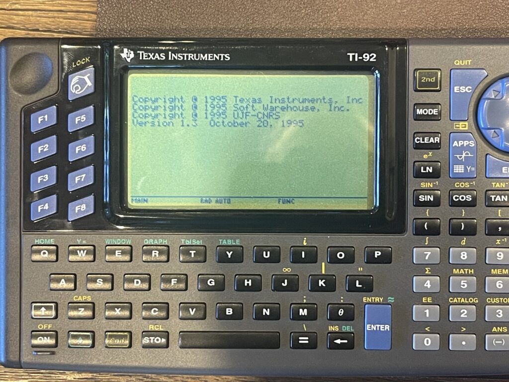
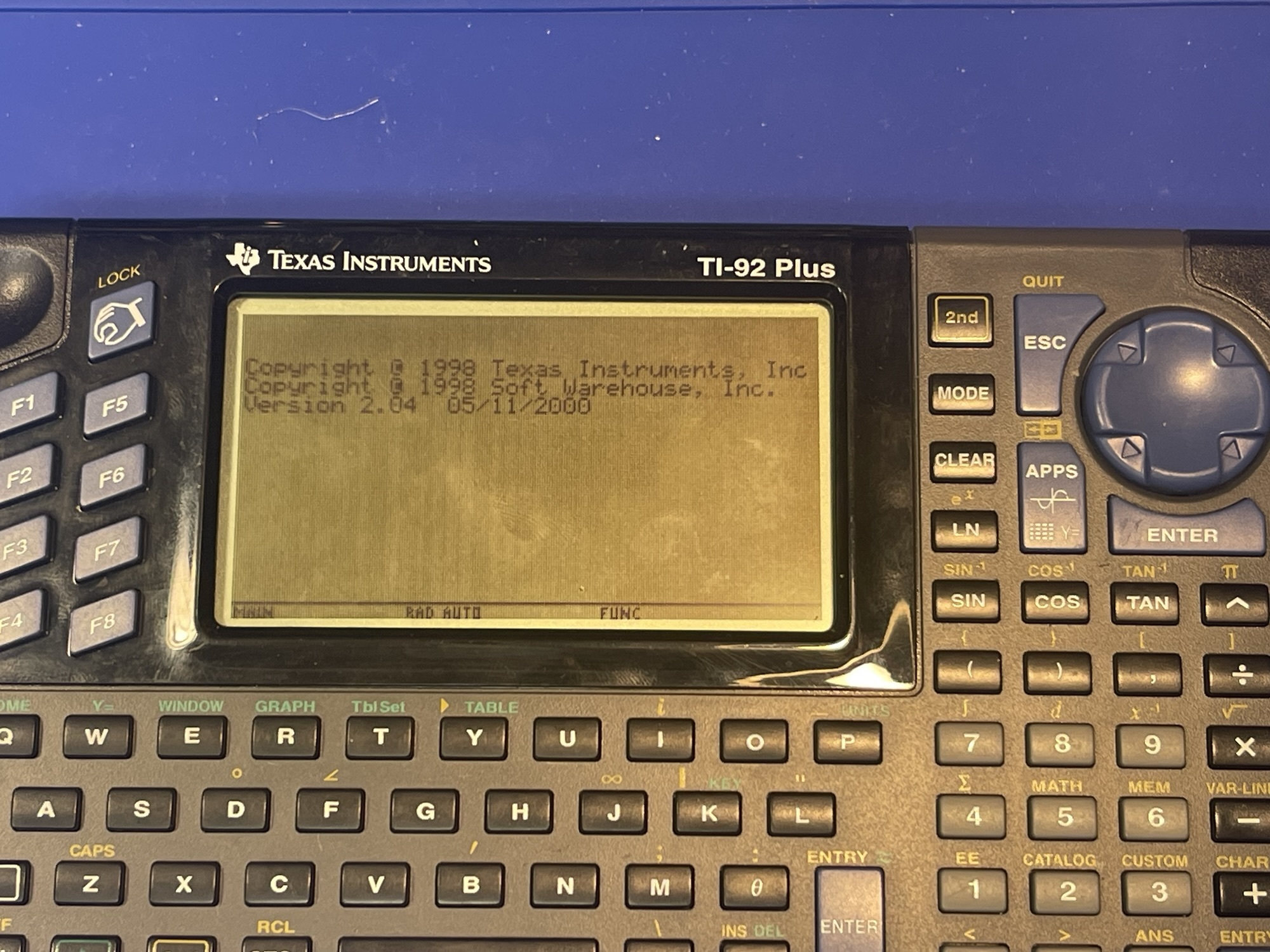
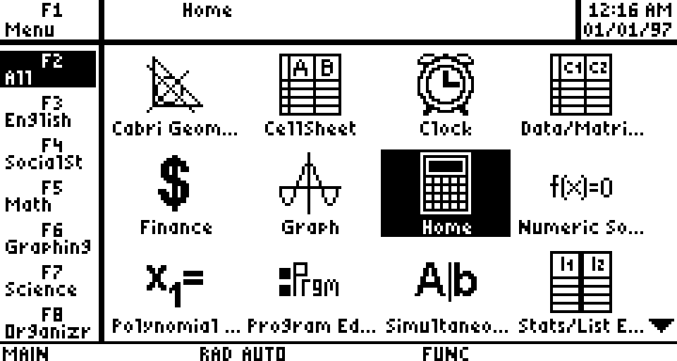
Texas Instruments TI-92 Plus Graphing Calculator
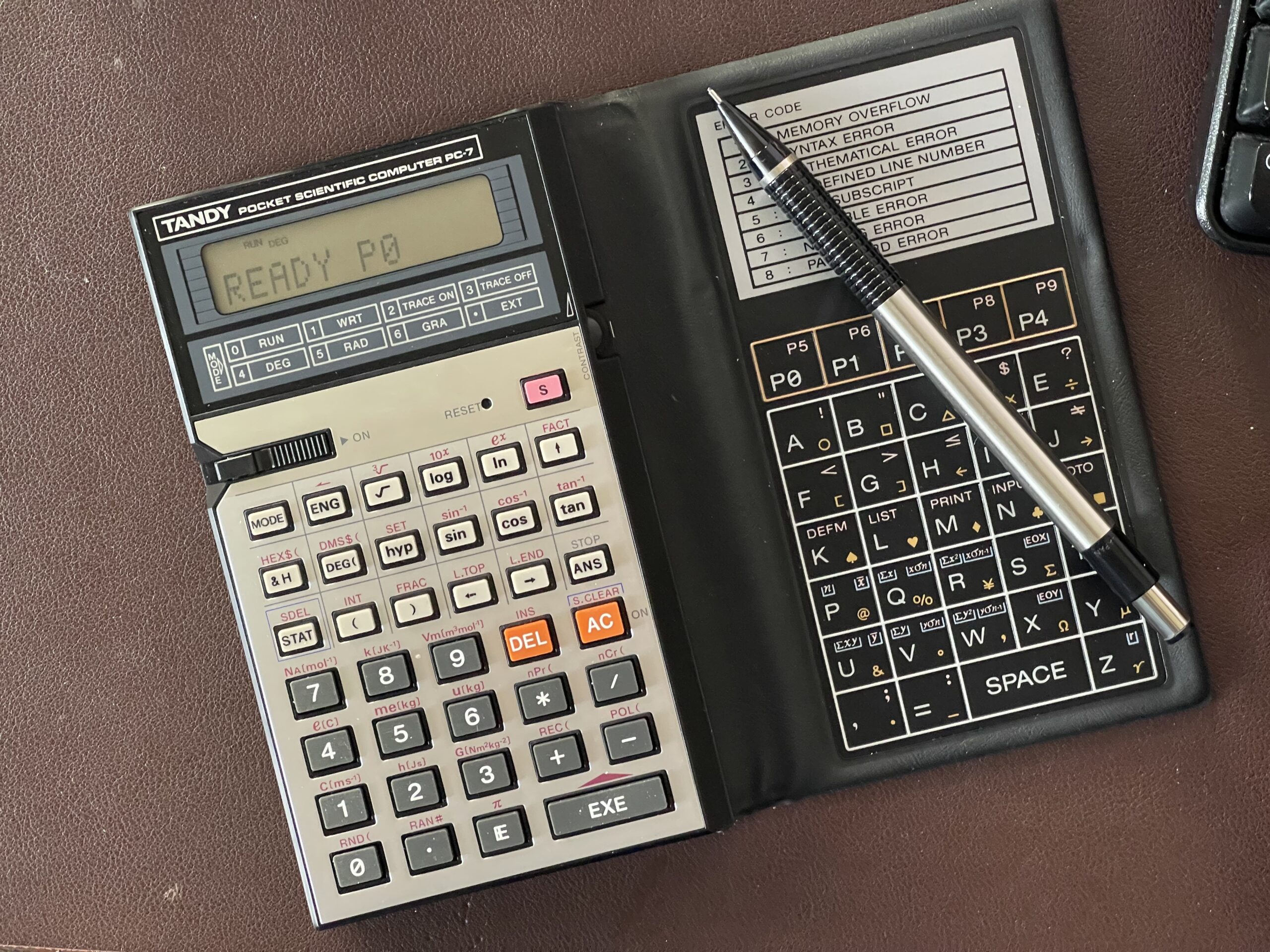
As I have written in previous posts, my first programmable calculator was the Tandy PC-7, which happened to be the least capable pocket computer from the entire Radio Shack line.
The PC-7 had no peripheral options, only 2KB of memory for user programs (1,568 bytes available to the user after a reset), and a one line LCD screen. Not to mention the cumbersome membrane-style keyboard for the alpha keys.
TI-85 Graphing Calculator
In the early nineties, I had a high school math class that required TI graphing calculators, as the entire class was centered around functions, graphing, and statistics. The recommended model was the TI-85. At the time, the TI-85 calculator had a retail price of $99.99.
My parents purchased one for me and I had previously limited experience with these types of calculators. Years back we used a TI calculator model that supported fraction notation for adding, subtracting, dividing and multiplying, which I thought at the time was a great feature. Compared to the PC-7, the TI-85 was completely different in so many ways.
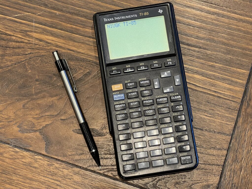
The TI-85 had a dot addressable multi-line screen, plenty more memory than the PC-7, durable plastic keys which were far easier to type on, and a hard plastic cover to protect the device when not in use. Further, it ran on 4 “AAA” batteries, instead of two CR-2032 button style batteries like the PC-7. It also had a small button-cell lithium backup battery – this allowed me to change batteries without losing my programs and memory contents. This was not something I was able to do on the PC-7.
The screen resolution of the TI-85 is 128 by 64 pixels. There is no buzzer on this model and no cassette or printer interface like the previous generation of Casio and Sharp pocket computers I had experience with. This model was meant to be used in an education environment, specifically algebra, trigonometry, statistics and related areas.
There were alpha keys characters, accessible via the Alpha key, but not as dedicated keys.
These were programmable in a form of BASIC, but vastly different than the BASIC on the Sharp and Casio pocket computers I am familiar with. In fact, I specifically remember not really being interested in programming anything on this model because the BASIC dialect was so much different than anything else. Further, the owners manual did not really delve into the specifics of every function and command.
This post is a bit of a departure from my previous posts on Casio, Sharp, and Radio Shack pocket computers, advancing forward about a decade. There is a project I have been working on for a few months (as of the writing of this post) and I decided to incorporate this line of graphing calculators into that project.
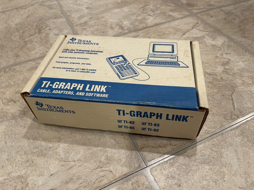
TI Graph Link
Most interesting of all, the TI-85 had a link port at the bottom which supported sending and receiving variables, programs, and backups directly with other units. It even included the link cable, which was a simple 3 wire 3/32” or 2.5mm audio style jack.
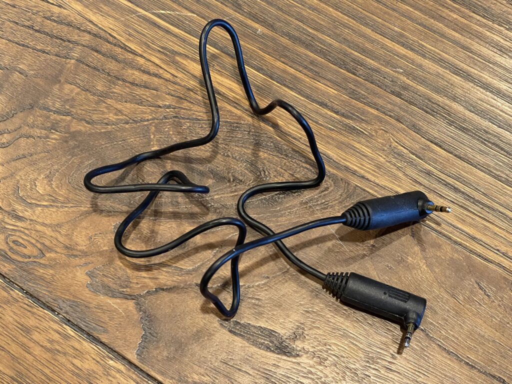
TI included this graph link cable in the box, not only for the TI-85 but all other models that shared the same interface. This was not something that needed to be purchased separately.
This and the fact that it was not a proprietary connection format most likely contributed to its popularity and use in the field. A standard 2.5mm stereo patch cable would work all the same.
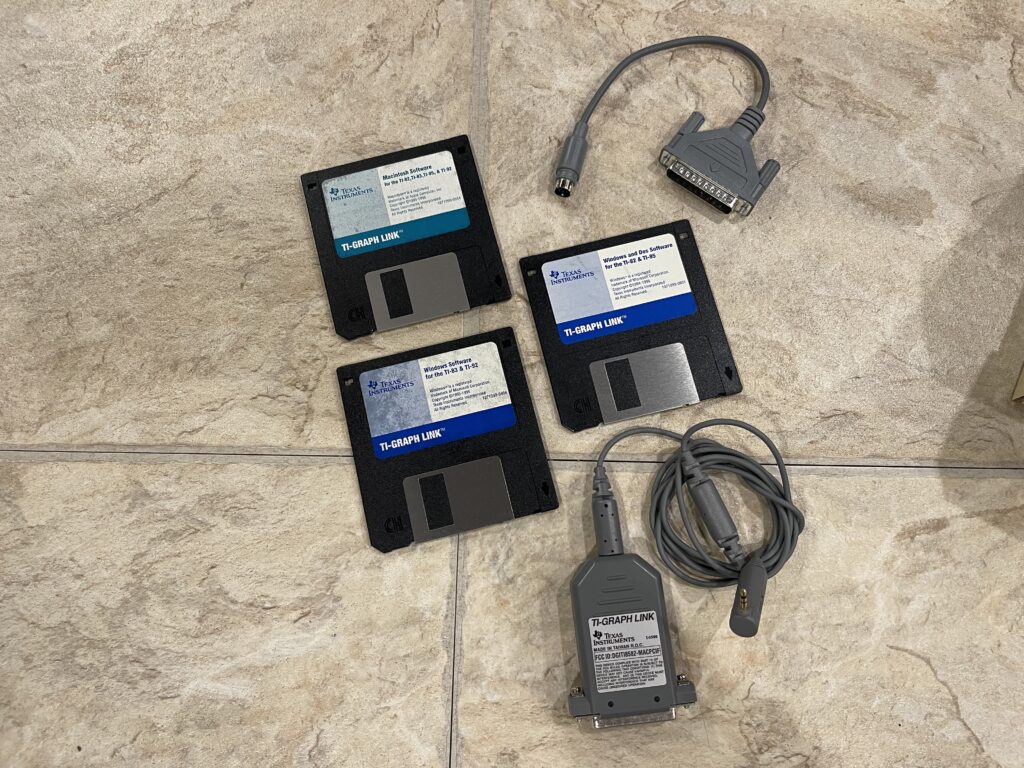
Back then, I had purchased the TI Graph Link kit which provided connection from these calculators to a PC or Mac. This link kit was later referred to as the “Gray Link” cable, as there would be other iterations of this connectivity kit in the future.
I actually used that link kit later in college for a few projects, mainly to take snapshots of the screen and print them.
I had also used the graph link to download assembly games (Tetris and a few others). There was a known buffer overrun hack that would allow assembly programs to be downloaded and executed, which allowed these games to be created, shared, and run.
The gray link cable had the 2.5mm TI Graph Link connector on one end and a 25 pin RS-232 interface on the other end. This required the computer to have an RS-232 port, either a 25 pin port or a 9 pin port. It would power itself off the hardware flow control lines on the serial port.
The kit also came with a Mac bus connector to RS-232 adapter so that the link cable can be used with a Mac. Included were three 3.5″ floppy disks with Windows, DOS, and Mac link software.
The advantage to this cable (at the time) was that it converted the TI link protocol to a standard RS-232 serial connection – the pic or microcontroller inside the cable handled the translation, and the software on the PC saw the link as a standard serial connection running at 9600 baud. This allowed me (at the time) to connect that TI-85 to a packet TNC via this cable, and using a terminal program written for the TI-85 in assembly to interface with the TNC.
Other variants of this link cable, such as the “black link” version did not perform this serial conversion and required the host computer to toggle control lines on the serial port via software.
TI-86 Graphing Calculator
In college I bought a TI-86, which had a slightly improved screen and more memory (96 KB). The resolution was the same as the TI-85, except with a sharper contrast LCD screen and less reflectivity from the plastic screen protection.
The graph link cable was compatible with this model also.
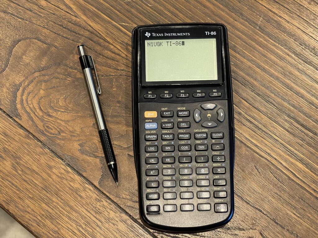
The TI-86 at the time was around $119. This version had more rounded edges and an updated look.
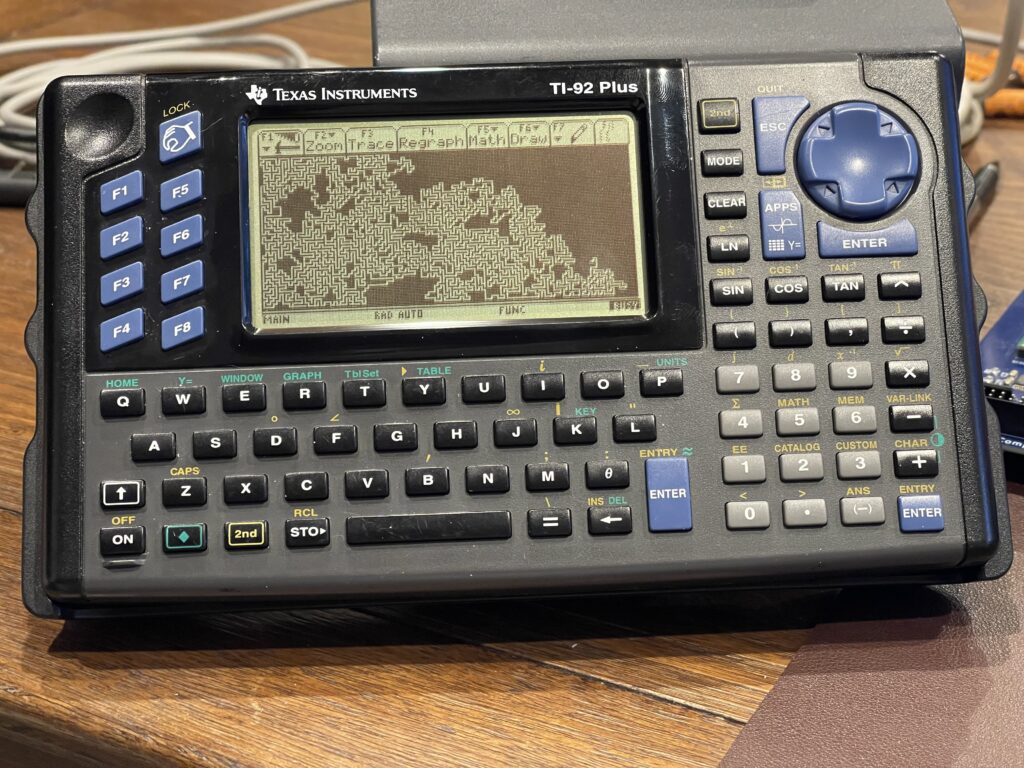
TI-92 Graphing Calculator
Around the same time, I had seen the TI-92, which was a beast compared to the TI-85 and TI-86. It had dedicated “qwerty” keys, a bigger screen, more memory and it was a bit faster.
At the time, the TI-92 was quite a bit more expensive. It retailed for between $179.00 and $250.00 depending on when it was purchased. Needless to say, this out of my price range for a calculator as a college student.
The TI-92 has a Motorola 68000 processor while the TI-85 and TI-86 have a Z80 processor. The TI-92 also had the same graph link port as the previous models had.
This model (and it’s variants) also continue with the tradition of having a removable hard plastic cover.
TI then released two successors to the original TI-92, the TI-92 II and the TI-92 Plus. The TI-92 Plus had a much improved screen and flash memory for firmware updates and application installation.
The later versions of the TI-92 that had removable ROM modules which could be replaced by a module with flash ROM and more RAM. TI sold these as upgrade packs which could be purchased for compatible TI-92s and installed, giving those TI-92 owners an instant upgrade to the TI-92 Plus firmware.
The successor to the TI-92 line was the Voyage 200.
eBay Purchase
I recently saw a listing on eBay for four TI-92 calculators “for parts only” for $46 plus a reasonable shipping fee. I zoomed in a bit on the listing photos looking for specifics to see if there was any obvious screen damage, general condition, and if any where the TI-92 Plus model.
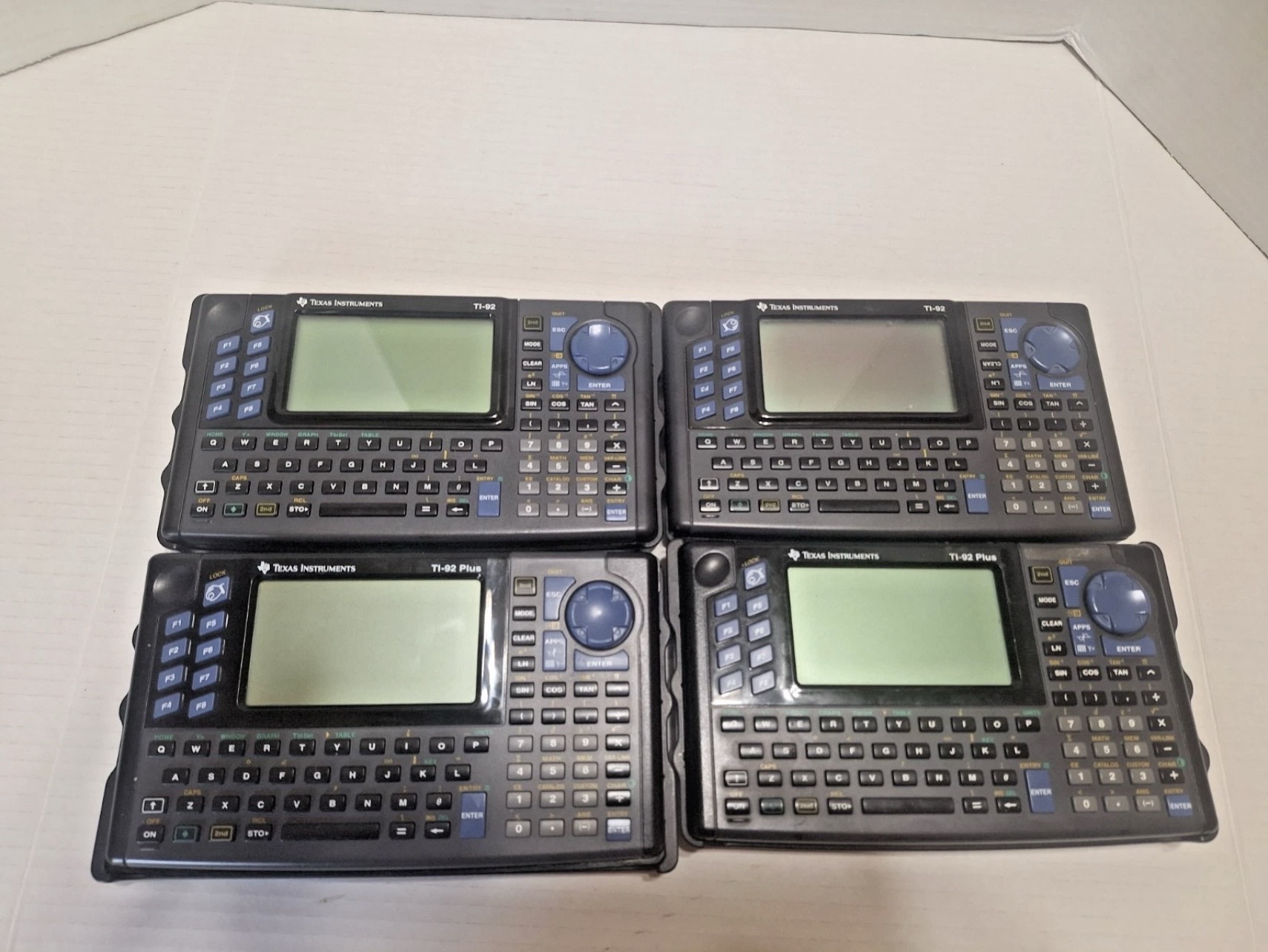
The photos indicated two of them were a plus model, and the other two were most likely the first model (more on this difference later).
I pulled the trigger and bought these as parts only, taking a small risk that none of them would work, and none would be fixable.
Repairs
All of the units ended up being in fair to good condition, and two were in fact TI-92 Plus models.
I started working on repairing the non plus models first, so that I could become familiar with the details on what to look for and practice some repair ideas.
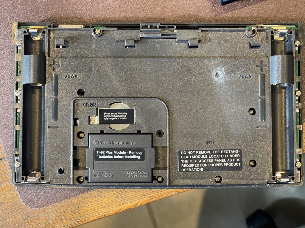
These models are very easy to remove the back cover to expose the PCB and battery contacts. There were quite a few Philips screws holding the back cover to the front cover.
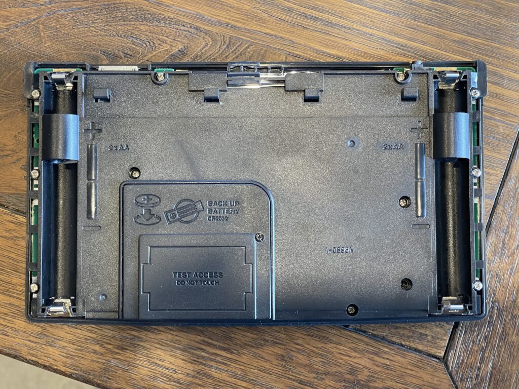
The non-plus models have a “Test Access” cover, which is held on with a long thin philips screw. This does need to be removed in order to take the back cover off.
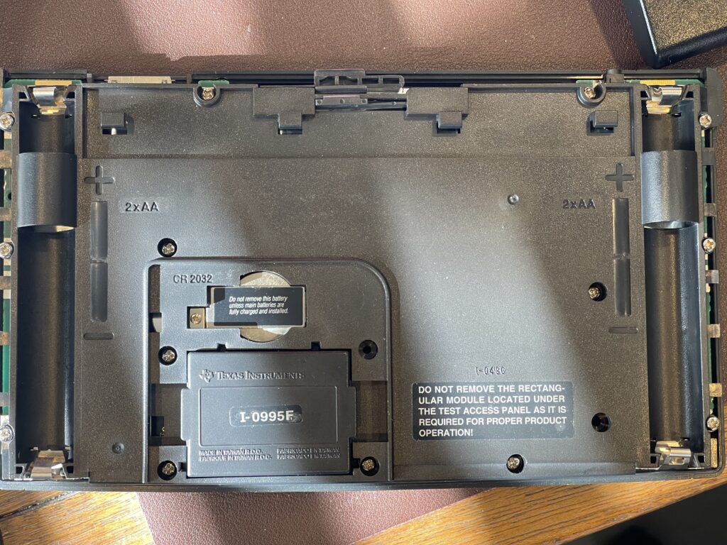
Once the “Test Access” cover is removed, one of two options will be exposed below, depending on the hardware revision of the TI-92. The later hardware revisions had a removable system ROM pack, as shown above.
The earlier hardware revision had a soldered-in system ROM (underneath the metal shielding, which I have removed for repairs in progress):
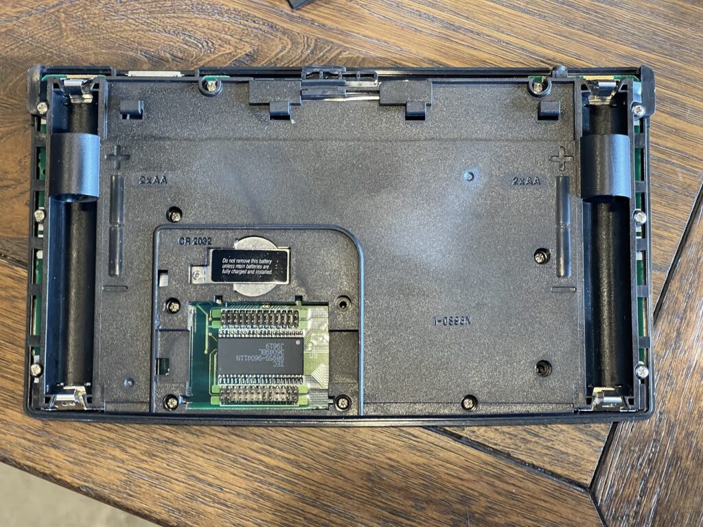
Note that these versions also have posts for adding a ROM pack. If there is a removable ROM pack, it must be carefully removed before the back cover can be removed.
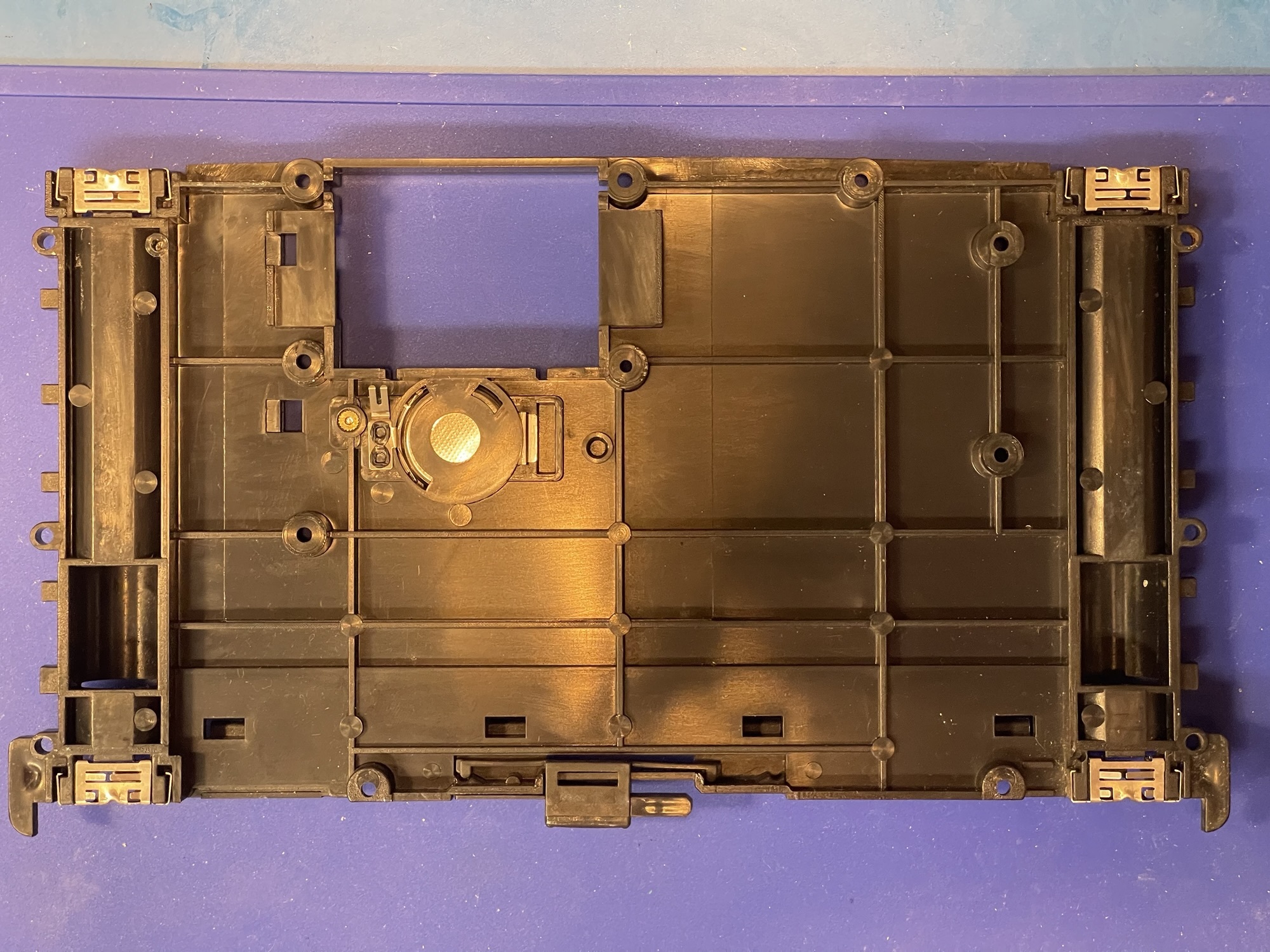
The 4 “AA” batteries are held in place by the back cover with four terminals which make contact with the back of the PCB. The CR-2032 backup battery is also held inside the back cover with a contact and spring to make connection on the back of the PCB.
The back of the PCB has a shield around almost all of the surface, which is held in place with two strips of adhesive on the sides and contacts with the board via some of the screws holding the case together.
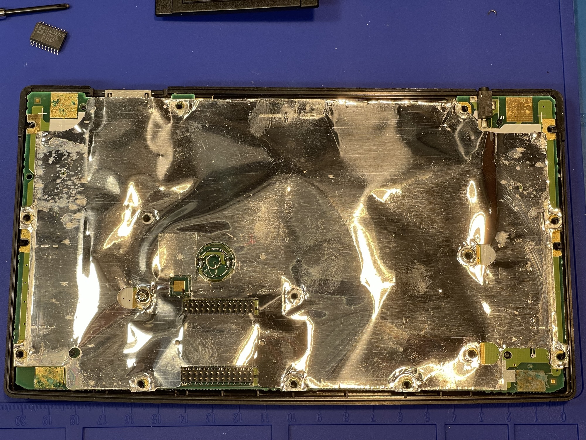
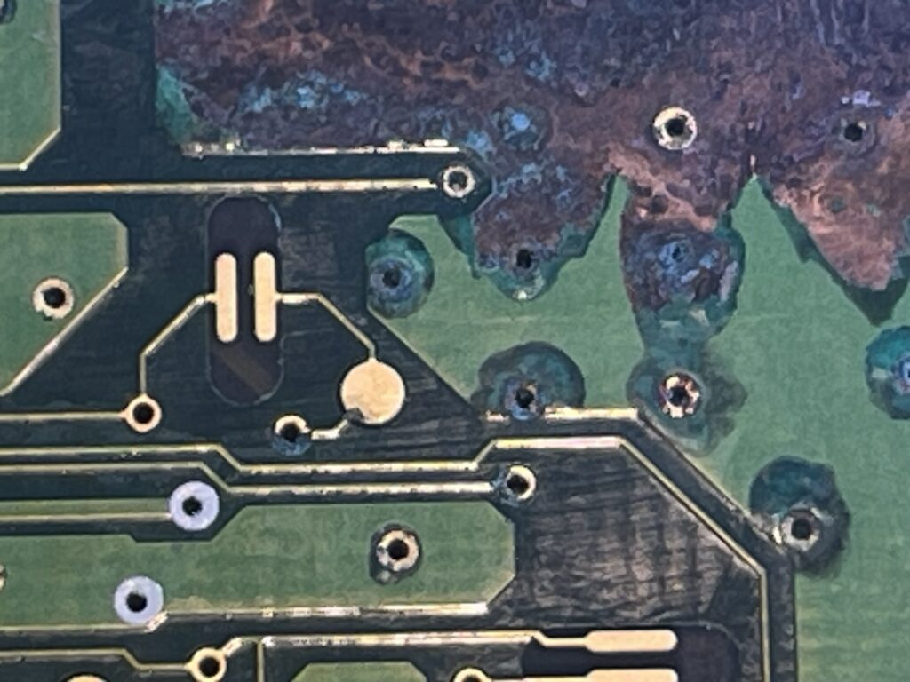
Once I removed the back cover, I could immediately see why these TI-92s were not working. If batteries are left in the unit for long periods of time, they eventually leak. The corrosion then starts around the four battery contacts on the PCB.
This corrosion is easily spotted almost right away. The shield is easily removable, at which point I could see how far the corrosion had made its way into the board. If the corrosion spreads beyond the battery terminals, it could travel to the ROM posts, and if the unit has a removable ROM pack, the posts could be brittle and break off when removing the ROM pack.
This is repairable, should it happen. The female connection strip on the ROM pack can be removed with hot air, the broken post poked out, then the connection strip can be soldered back in place.
Broken pins will need to be repaired by replacing the pin header strip, either from a donor board or via replacement part from an electronic component supplier.
I removed the corrosion from the battery contacts using distilled white vinegar and a swab, then some cleaning with IPA. I then used a fiberglass pen on areas where the corrosion was heavy.
The first unit was an easy repair, and once I reassembled the case, it worked perfectly:
The second TI-92 was fixed as well, with similar corrosion issues as the first unit.
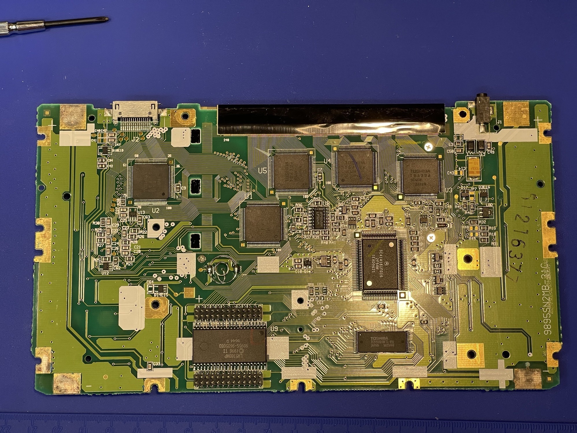
Fixing a TI-92 Plus
The TI-92 Plus was an enhanced version of the TI-92, adding flash ROM and more RAM. It also had an improved LCD display.
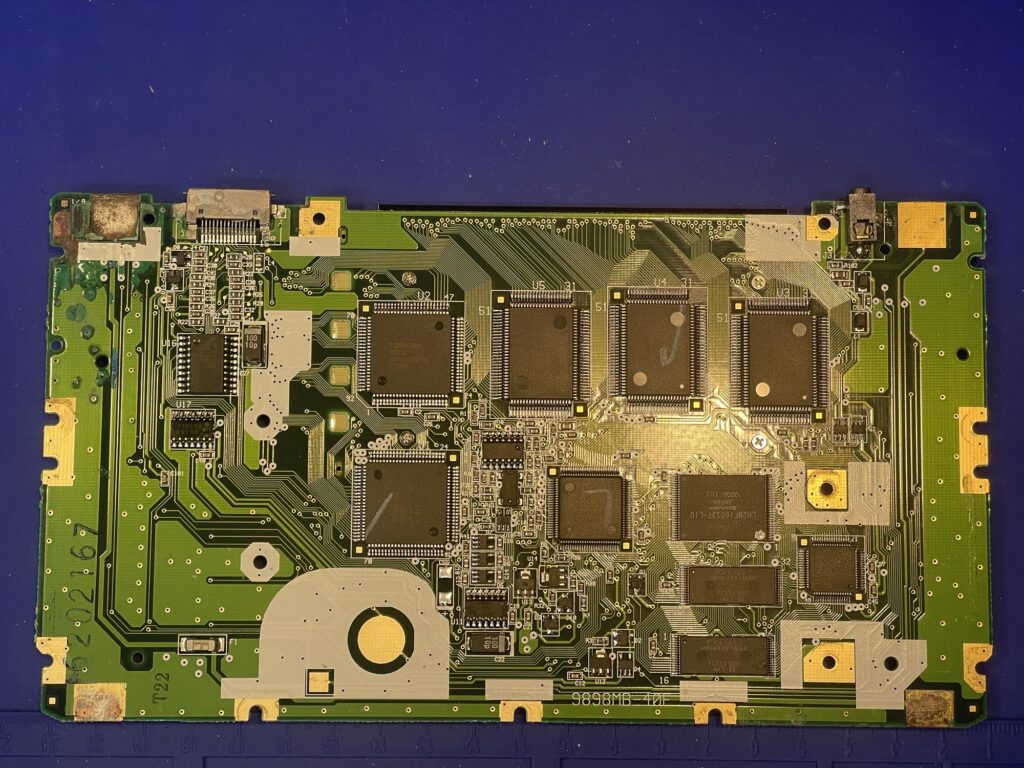
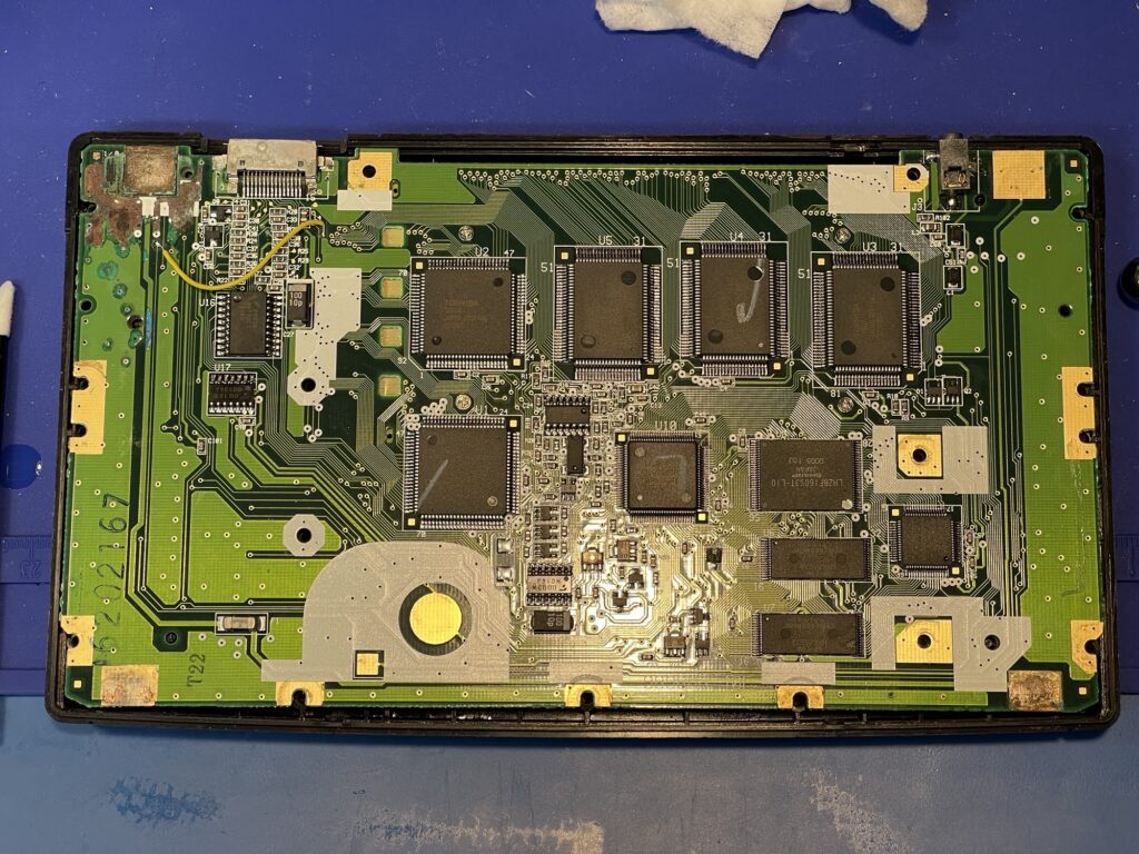
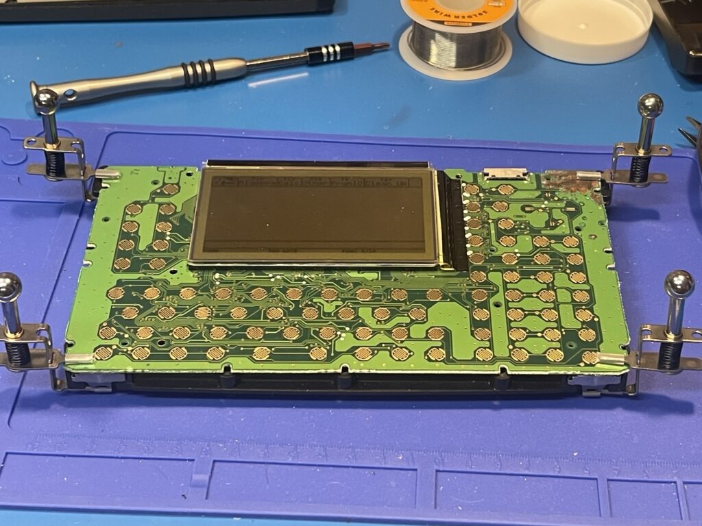
Now that I had successfully repaired two TI-92s, I was ready to work on the two TI-92 Plus units. The TI-92 Plus is held together with similar screws as the TI-92 model, but these have a star head. Further, there is no system ROM nor ROM pack, as this is now on the PCB in a different location.
There are quite a few other differences in the TI-92 Plus, mainly no removable flash ROM and RAM, a smaller footprint Motorola 68K processor and all of the traces on both sides are completely different.
The first TI-92 Plus had far heavier corrosion than the first two units I repaired. I used the same methods to clean up the PCB:
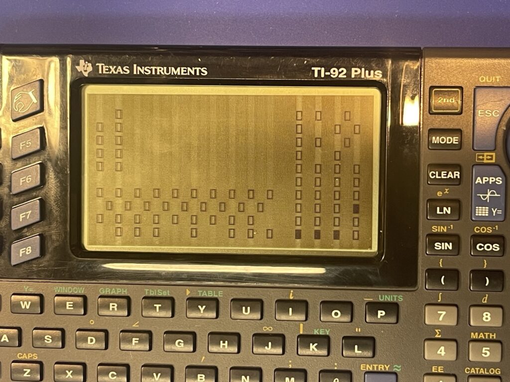
The unit powered on, but the contrast was a bit too dark. I was unable to adjust the contrast lighter, but I was able to adjust the contrast darker. I suspected an issue with the keyboard, so I ran the built in keyboard check routine and found a few keys which did not work.
I took the unit apart again and visually inspected the traces for the keyboard and on both sides of the PCB. I was unable to visually spot anything suspicious, so I began to probe the traces with a DVM.
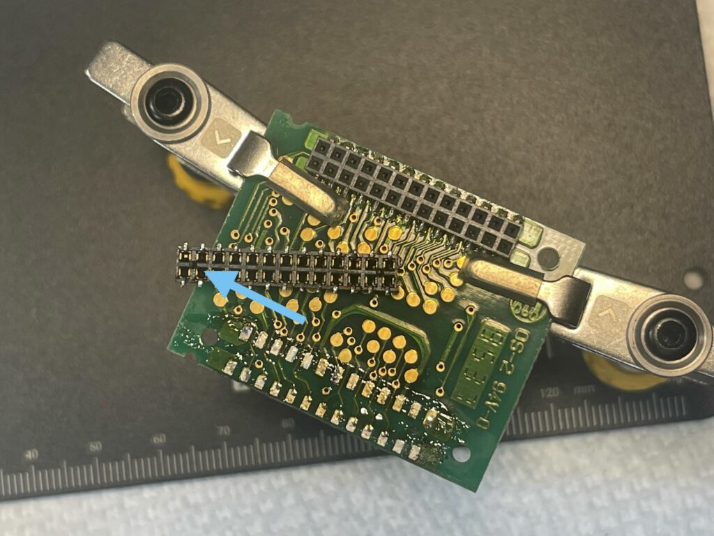
I started checking the areas near the corrosion, and found a continuity break on one particular trace on the upper right corner of the PCB:
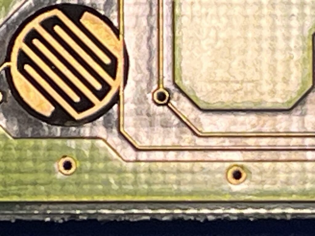
Most of the broken traces were in the area where the ground planes are connected, but one of the other broken traces was for the upper right keys on the keyboard.
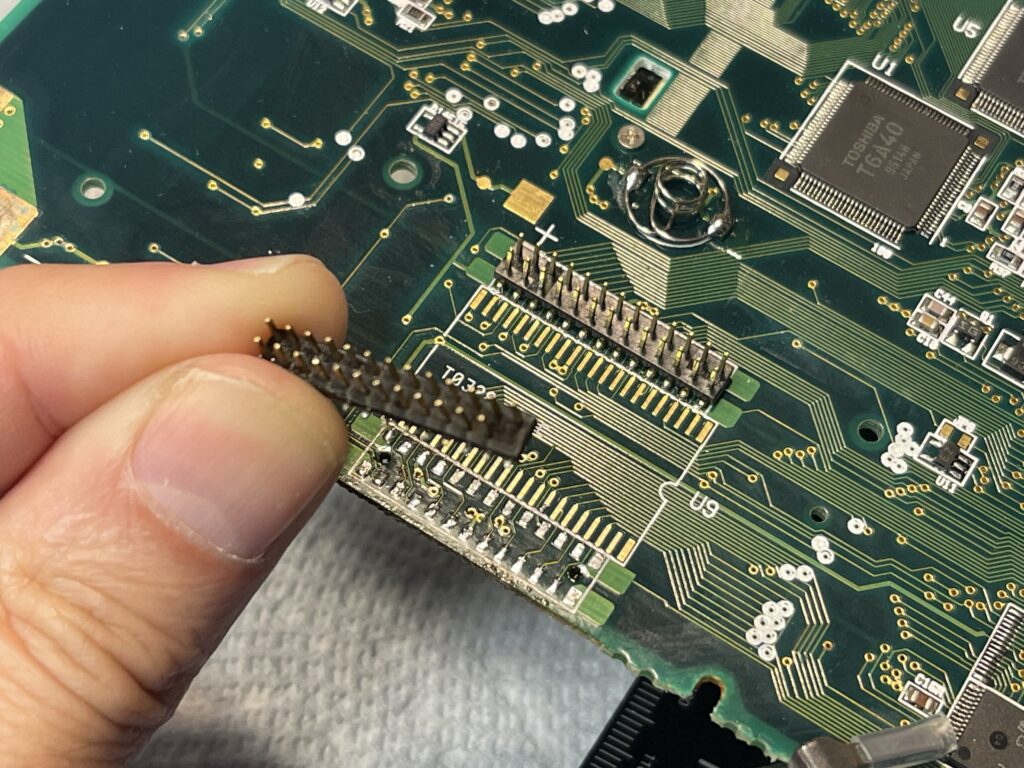
Because this break was under the keyboard rubber pad, I decided it would be easier to tack a bodge wire on the other side of the PCB to bridge the broken connection. I probed around the board to find two places that I can tack a bodge wire to:
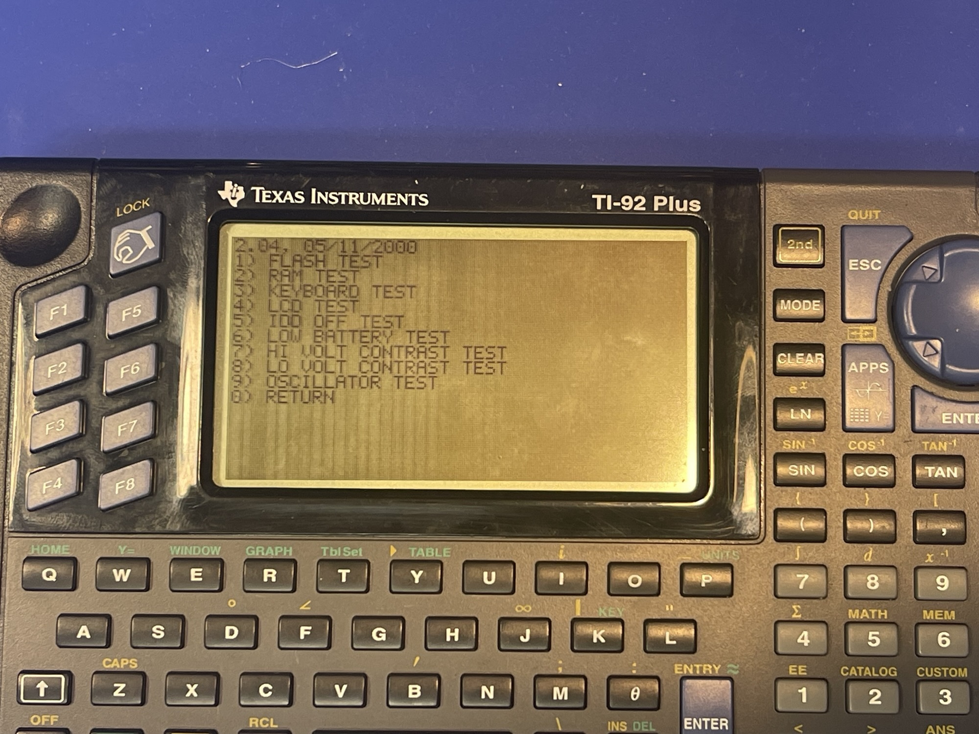
I ran the keyboard test routine again, and this time the top right corner keys worked! The version and test routines can be accessed by pressing F5, then the diamond, then the right parentheses key. Then press S to open the test menu.
Now I had only 4 more keys left to repair. I scoured the board further and to save some time, I rigged up the battery cover to the back of the PCB with some clips so that I can inspect, try a bodge wire, and check the result very quickly:
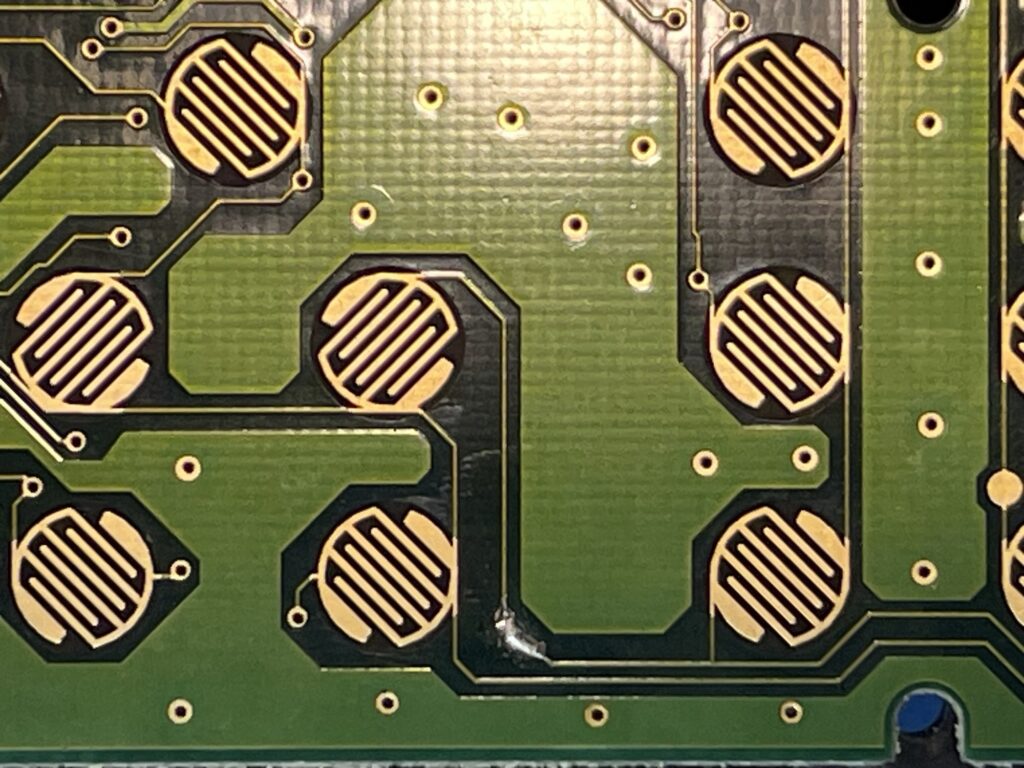
After what seemed to be about an hour or so, I found another broken trace:
I could not easily find any other places to tack on a bodge wire, so I added a bridge using solder:
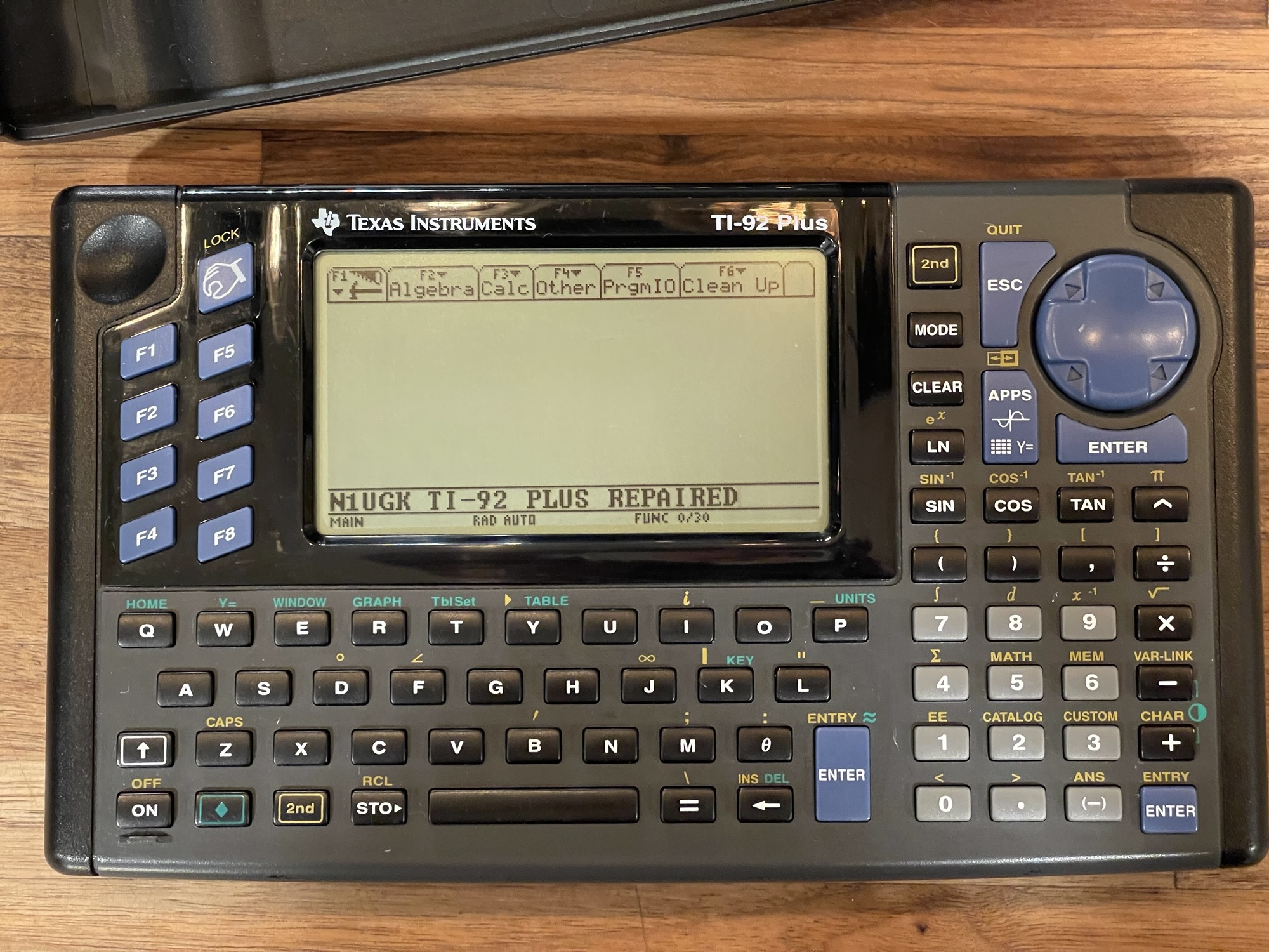
Success! The keyboard test worked, and I was able to adjust the contrast (and use all of the relevant keys). This TI-92 Plus was successfully repaired.
The second TI-92 Plus had minor corrosion, as the batteries left inside had surprisingly not leaked all that much.
Broken Graph Link Connector
Two of these units had broken graph link connectors. These are 2.5mm “stereo” sockets and I was able to use a part that I already had on hand for the PCUI (Pocket Computer Universal Interface) project I am working on. I posted a video on this repair which is embedded below:
Since I need the graph link ports working on these units in order to add support for these models for the PCUI project, these needed to be repaired.
TI-92 Plus Flash Updates
Because the TI-92 Plus had Flash ROM, it could be updated using a graph link cable and TI software for a PC or Mac. Unfortunately TI no longer supports these models, so the software update will no longer function using the TI software.
Luckily TiLP supports these TI models and the firmware file can be found online. I updated the firmware on both TI-92 Plus units using TiLP for windows and the silver link cable:
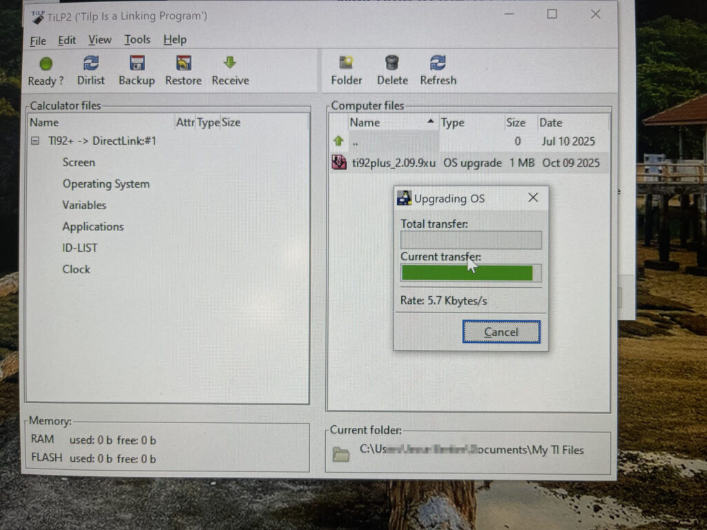
The silver link cable is a USB version of the link cables sold in previous generations. These are easy to come by these days, however, they are a bit expensive.
TI-92 Plus Overview
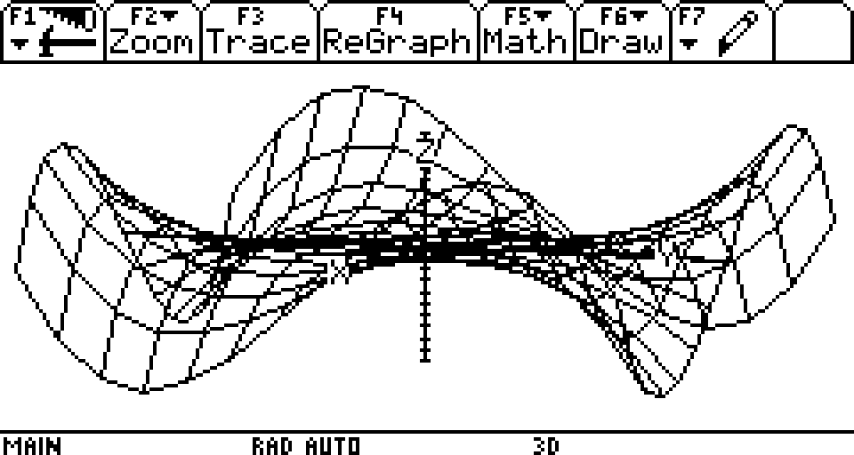
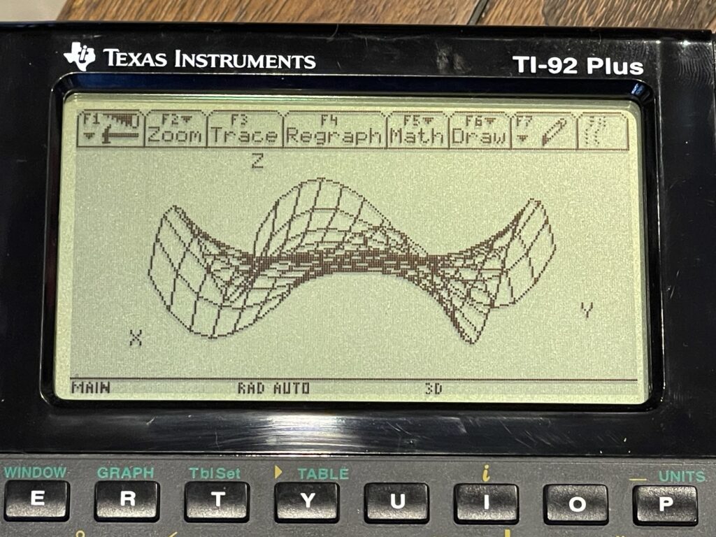
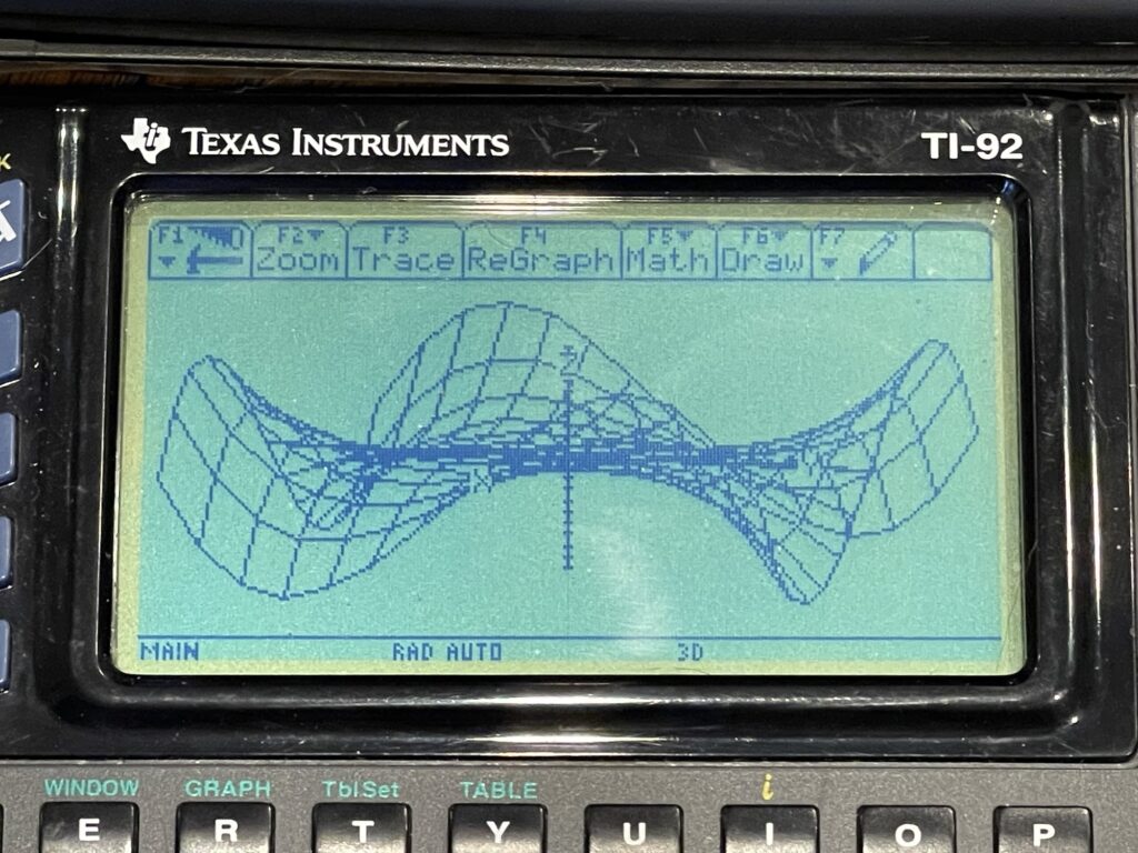
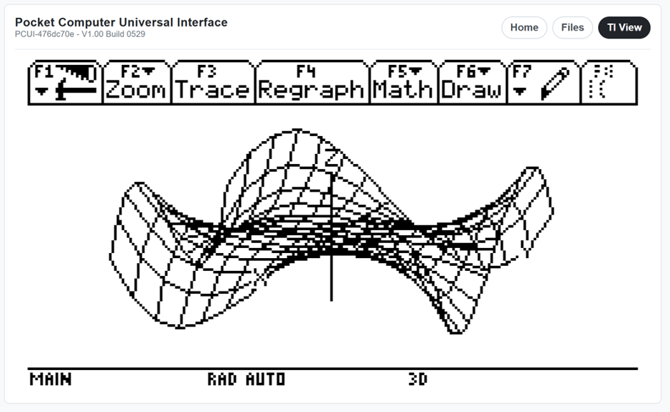
The TI-92 Plus (as well as the original TI-92) is marketed towards students in algebra, geometry, and calculus. From this point forward, I’ll refer to the TI-92 and TI-92 Plus as simply the “TI-92”, unless otherwise noted. The major enhancements over the previous iterations of TI’s graphing calculators include 3D graphing, shading, symbolic equation representation and more.
LCD Display
This is all possible in part due to the increased LCD size and resolution. The TI-92 boasts a 240 by 128 pixel LCD display, 68KB of RAM, and 136KB of ROM. The TI-92 Plus expands upon that with more memory – 256KB of RAM and 384KB of Flash ROM.
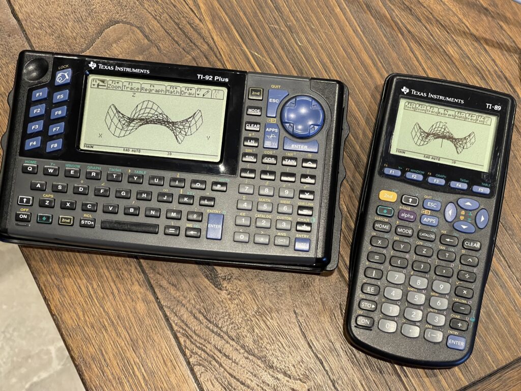
The LCD display on the TI-92 Plus has far better contrast than the TI-92, as can be seen in the comparison below:
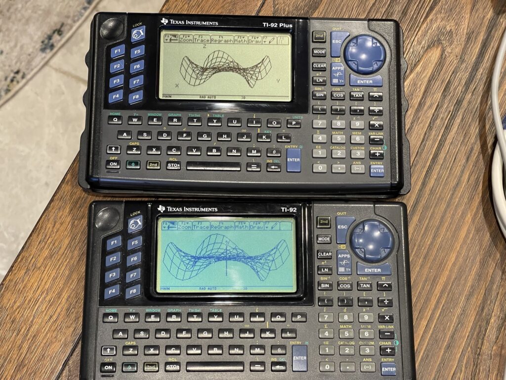
Most of the improvement comes from a better contrast LCD screen, and the rest from the lack of plastic protective cover over the LCD.
Keyboard
Because of its “qwerty” style keyboard, the TI-92 was not allowed in many standardized test environments. It was considered to be a computer rather than a calculator. TI responded to this by releasing the TI-89 which was a form factor that resembled the TI-85 and TI-86. The software and capabilities were similar. In fact, they are so similar that TI released a single instruction manual for both models.
However, due to the smaller form factor, the LCD resolution was reduced from the TI-92’s 240 by 128 resolution to 160 by 100. Interestingly, since the software for the TI-89 and TI-92 are nearly identical, the TI-89 has the same internal buffer for the larger size display, but ends up using only the top left corner of that buffer.
Software
TI released software application downloads for the TI-92 Plus which could be downloaded and installed into the Flash ROM. Many of these are still downloadable today directly from TI here. These applications are written in Motorola 68K assembly. TI also released a developers guide for how to write software applications for this platform.
Accessories
Unlike the previous generation Casio and Sharp pocket computers (and other eaerlier TI calculators), the TI graphing calculators did not have dedicated printers, cassette interfaces, nor floppy disk drives for saving programs and data. Instead, the graph link port and computer cables were the mechanism to backup and restore programs and data and to print screen shots. This of course requires a PC or Mac and a graph link computer cable.
This makes sense, because the previous generation pocket computers were released before there were standard PC interfaces and operating systems. These TI graphing calculators were released at a time when RS-232 ports were commonplace, used for modems, mouses, and other peripherals. Further, most TI purchasers likely had a PC or Mac at home as well.
Since these calculators were geared toward an academic environment, TI produced and sold classroom accessories such “View Screen” kits. These would connect to the display port on the TI-92 and connect either directly to an HDMI input on a television or projector, or, feature a transparent large LCD screen that can be placed on an overhead projector.
Models released before the TI-92 would have a special unit produced which had a chunky display port module underneath the top half of the unit. This would plug into a transparent large LCD screen for placement on an overhead projector.
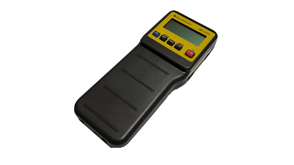
Calculator Based Laboratory (CBL)
It is worth noting that TI released sensors and data collection devices for use with these TI calculators. The devices would plug into the TI via the graph link port and sensors would plug into the CBL device.
BASIC Programming
I had mentioned earlier that the BASIC dialect on these TI graphing calculators is very different than BASIC on Sharp or Casio pocket computers:
:0→temp
:1→i
:Lbl TOP
: temp+i→temp
: If i<10 Then
: i+1→i
: Goto TOP
: EndIf
:Disp
For example, as seen in the sample block above, “Disp” replaces the familiar “PRINT” statement and variable assignment is done via the right arrow or “Store” key (→) as opposed to the familiar syntax “A=3”. There are many other variations as well.
Another major change with the TI programming language is there are no line numbers. However, labels are supported, which actually improves program readability. Further, there is no concept of GOSUB, but, you can call other programs and pass in parameters, more like “C” programming.
All variables, lists, matrices and other data types are “global” by default, unless you use the “local” statement in your program. This allows easy sharing of data between programs or subroutines.
This is why, historically, I never really had any interest in BASIC programming on these models. I do understand why TI had such a different approach their programming language for these models. Since these were geared toward education, all of the features and functions of the language are to support the graphing, calculus, algebra, statistics, and geometric functions of these models.
The programming language supports custom menus as well as nearly everything that can be done via the keypad and prompts in the user interface.
The editor for programming is luxurious. It is multi-line and works just like a text editor. This is very similar to the Casio PB-1000 for example.
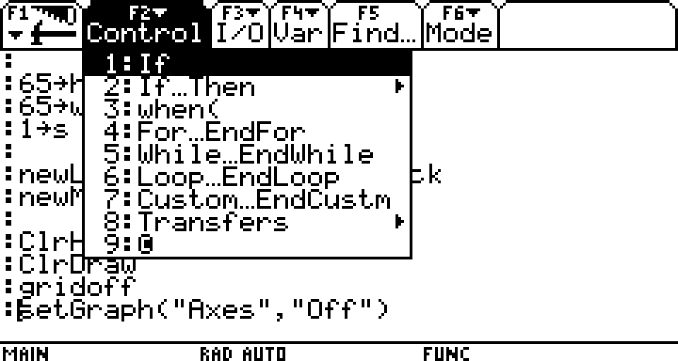
The menus while in the program editor offer some hints and easy reference for functions, symbols and other items commonly needed when writing a program:
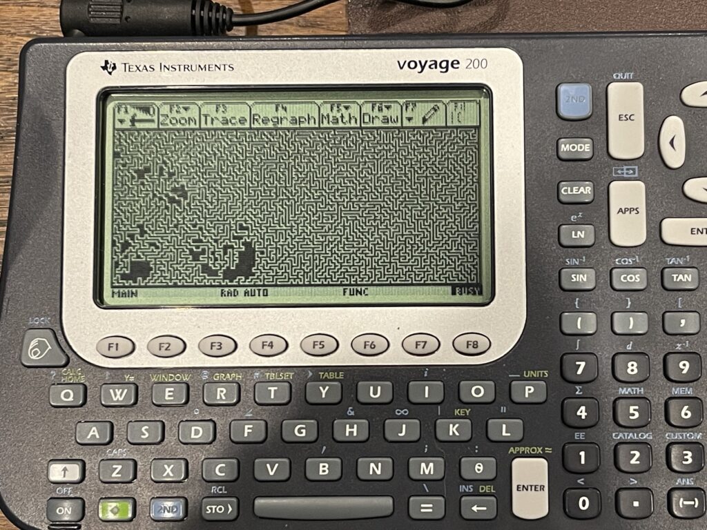
Maze Program
A program that is interesting to write for pocket computers is a maze program. Since this is the first TI graphing calculator I attempted to write a maze program for, I had initially no idea if it would be possible.
The TI-92 has a dot addressable display. The physical pixel dimensions are 240 by 128. TI provided several methods in BASIC for turning a pixel on or off, flipping a pixel state, drawing a line, and detecting if a pixel is on or off. This means that I would not need to track pixel state in memory.
With the TI-92’s screen and programming functions mentioned above, I can generate a maze directly on the LCD display. The TI-92 has plenty of memory to work with, unlike many of the earlier Casio and Sharp models I have experimented with. This means I do not need to worry about creative memory usage for this version.
The simplest algorithm to use for maze generation is the backtracking algorithm. It can easily be programmed in BASIC.
The algorithm requires the canvas size to be odd in both width and height, for example, 19 x 19, and not 20 x 20. The requirement for the canvas dimensions being odd instead of even is due to the interior lines or blocks needed for the maze. For example, lets consider a maze on a canvas size of 27 x 3:

The maze itself has a single pathway, given the height of the canvas is 3 pixels, and the pathway is in between the top and bottom walls. The next incremental height we can consider would be 5 pixels high, not 4 pixels. The same can be said for the width, for example flipping the maze dimensions to a 3 x 27 canvas. Therefore, the height and width of the canvas must always be an odd number.
A maze generator would need an actual canvas to work with (either on the screen, in memory, or both), and it would need a stack to push and pop in order to track where the algorithm has “walked” before. The algorithm will “push” to the stack as it walks uncharted territory on the canvas, and “pop” from the stack when it needs to back up (if it hits a wall or adjacent open space). The backtracking algorithm randomly chooses a direction with each step, with one of four possible directions (up, down, left or right). It will not be able to choose a direction that would hit a wall or an adjacent open space. Therefore, if no directions are possible for travel in the current position, it must “backtrack” until a direction is possible.
Once the algorithm reaches back to it’s start position, the maze is complete. The start position is randomly chosen, and must be an odd number for the x and y coordinate. The odd numbered coordinates are spaces marked open during traversal of the path, and the even numbered coordinates become the walls of the maze. Therefore, each step in the “walk” is really 2 pixels away from the current position (skipping over the even numbered coordinates), in any direction. When a walk is performed and a position is marked as open, the adjoining position (the even coordinate) between the previous location and current location is also marked as open.
Below is an example of the backtracking algorithm animated with JavaScript from professor-l Elle:
There are some prerequisites which are needed for a pocket computer or graphing calculator to generate a maze using the backtracking algorithm:
- A dot addressable display and/or a printer
- Enough RAM to hold the canvas and/or stack for the desired width and height of the maze
- Random number generator
The TI-92 meets the prerequisites for a maze generator. However, the TI-92 nor any other related model ever had an official printer released for them. With a TI Link computer cable, it is possible to grab a screen shot from the TI and then print it on the attached printer, or save the image.
Memory Management
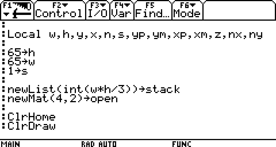
The larger the desired maze size, the more memory will be required to generate the maze. Since the TI-92 does not allow for direct memory access via PEEK and POKE, I will need to use the options available. Of course, the maze generator can be written in assembly, however, it can also be done in BASIC.
The TI does not directly support “arrays”, but it does have a list feature. The larger the maze, the more memory that will be required for the stack needed for the backtracking algorithm. If PEEK and POKE were supported, then only a single byte would be needed for each pixel on the canvas and stack value. However, I suspect the TI-92 uses multiple bytes to store the contents of each entry in the list. Since we have plenty of memory to work with, this can be overlooked.
The stack holds previously open spots when walking the canvas, using the backtracking algorithm. Since I need to track X and Y coordinates for the path, I need two positions in the stack for each coordinate. The total number of entries needed for the stack varies depending on the longest possible “path”. The worst case scenario would be a path which starts in a corner and winds along the outside walls until reaching the center. This of course is nearly impossible given the randomness of the direction chosen. Therefore, the stack size is chosen as an average maximum. I chose a stack size of 4 times the width of the canvas. I used one stack for the X coordinates, and another stack for the Y coordinates.
The TI-92 does not allow pixel manipulation on the entire screen. There is space needed at the top for the menu, and the bottom for status and mode. The actual maximum working space is 240 by 103. 18 pixels are required for the menu, and 7 pixels for the status display at the bottom.
Success
I worked through the algorithm to get it to work with the TI-92 and it was a success! Interestingly, the larger the canvas, the slower the access into the list object. Obviously a larger canvas would take more time to render, but it is not linear on the TI-92. Apparently access into a list takes more time the larger the list is. This is the reason I use two stacks instead of one single stack which would be twice the size of two separate stacks.
A Printer for the TI-92
Now that I had a working maze generator for the TI-92, I needed a printer in order to print out the maze. Unfortunately no printer was released that would directly connect to the TI-92, nor is there any built-in support for a printer. As I had mentioned earlier, printing could be done via a PC and a graph link cable.
I am working on a related project, the PCUI (Pocket Computer Universal Interface) for older Casio and Sharp pocket computers. The PCUI provides a printer interface as well as a cassette storage emulator. This allows printing, saving, and loading programs without the need for their original accessories, which are often hard to find and expensive.
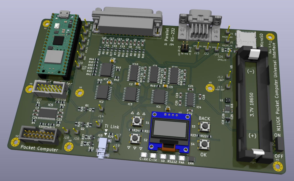
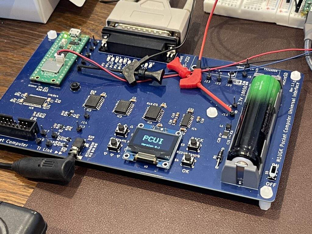
The PCUI is work in progress (as of the writing of this post) and is based on a Raspberry Pi Pico. The PCUI has both an RS-232 interface and a Parallel port. This allows for either a serial or parallel printer to be attached for printing for example. It also has a microSD card holder for storing of programs and data from pocket computers.
As part of my experimentation with these TI graphing calculators, such as the TI-92, I have added support for the TI series of graphing calculators which use a graph link connector. I added a 2.5mm graph link port on the PCUI and updated the PCUI firmware to add various features.
Printing Screen Captures
The first feature I worked on was the ability to pull a screen capture from the attached TI and print it. I added support for Epson ESC/POS thermal receipt printers for bitmap printing as well as standard line printers, including IBM ProPrinter support. It also supports scaling the screen capture up so that it can fill the page of the attached printer for a larger printout.
SendCalc Function
Since the TI-92 does not have specific printer support, I needed to come up with a method to be able to print from the TI calculators on demand from within a program.
The SendCalc function sends a variable to the attached device, usually another TI graphing calculator. In fact, in the owners manual for the TI-92, there is a sample “chat program” leveraging the SendCalc an GetCalc functions.
If the PCUI can receive the SendCalc function’s data, then it can use that function as a mechanism to print to the attached printer. SendCalc supports sending strings, numeric data types, lists, pictures, and more.
I could have simply directed everything received from the SendCalc function to the attached printer. While this certainly works, I added some support for commands as well. For example, the SendCalc function not only sends the variable contents, it also sends the variable name. I could leverage the variable name for changing print settings on the PCUI.
I added a few specific handlers for setting the print window and scaling factor from the TI. There is a reason for this, which I will explain further.
PNG Screen Captures
The PCUI saves all screenshots pulled from the attached graphing calculator as a PNG image to the microSD card. All of the images of TI screen shots in this post were saved by the PCUI. There is a setting to specify the scale of the PNG, such as 2x, 4x, etc. This is merely a convenience for pasting the images into documents or similar purposes without having to resize them manually.
USB Drive Passthrough
The PCUI has a microSD card passthrough feature which presents its microSD card to the host computer plugged into its USB port. The microSD card for example appears as an attached removable drive. This allows for quick copying of saved screenshots or programs and data, without having to remove the microSD card from the PCUI.
Gray Link Emulation
I mentioned earlier that the old TI Graph Link computer cables no longer work on modern computers, with the exception of the Gray Link cable and a USB RS-232 adapter.
Of course there were modern replacements by TI which were USB based. Today these can be found on auction sites, but they are a bit expensive.
The PCUI supports a Gray Link emulation mode. This mode bridges the TI link port on the PCUI and the virtual com port on its USB connector. This effectively turns the PCUI into a USB-based Gray Link cable.
This mode works with both TiLP and the TI software on the PC, if Gray Link or USB is selected as the cable type.
Sniffer Mode
Similar to the Gray Link emulation, two PCUIs can be connected via their RS-232 ports and a TI can be connected to each PCUI or a TI and a PC can be connected to each PCUI. It can then log the packets being exchanged between the devices and save them to the microSD card.
This is useful for debugging or sniffing the data exchange between the devices. It then allows discovery of how specific transfers work.
Supported Models
As of the writing of this post, the PCUI supports the TI-85, TI-86, TI-89, TI-92, TI-92 Plus, and the Voyage 200. More models will be added once I am able to acquire them for testing.
The PCUI firmware can be updated by placing it in bootloader mode (pressing and holding the boot button on the Pico) and dragging the firmware file to the attached drive that appears on the computer.
Printing the Maze using the PCUI
As I mentioned earlier, the TI-92 has a few rows of pixels both on the top and bottom of the screen which are reserved. When the maze is drawn via the maze generator program, the printout ideally should exclude those regions of the display at the top and the bottom of the screen.
With specific sequences of SendCalc functions in my program, I can direct the “window” and scaling for the PCUI to print, then tell the PCUI to grab a screenshot and print it to the attached printer.
The variable names the PCUI looks for and the purpose for each is outlined below:
prtx - the x offset for printing the screen capture
prty - the y offset for printing the screen capture
prtw - the width for printing the screen capture
prth - the height for printing the screen capture
prtscl - the scaling factor for printing the screen capture
prtscr - perform the screen capture and print it
In this example, if I have a 31 by 31 pixel maze canvas, and if the first 18 rows on the TI-92 screen are for the top menu, then the parameters to print just the 31 by 31 maze would be:
prtx - 0
prty - 18
prtw - 31
prty - 31
For the scale (prtscl) I use 100. The reality is, it is very unlikely I would need a 100x scale factor for printing these mazes, but the PCUI will scale until the printer’s maximum width is reached if a scaling factor of greater value is provided. A value of 100 simply results in the maximum scale possible on the given printer and maze canvas size.
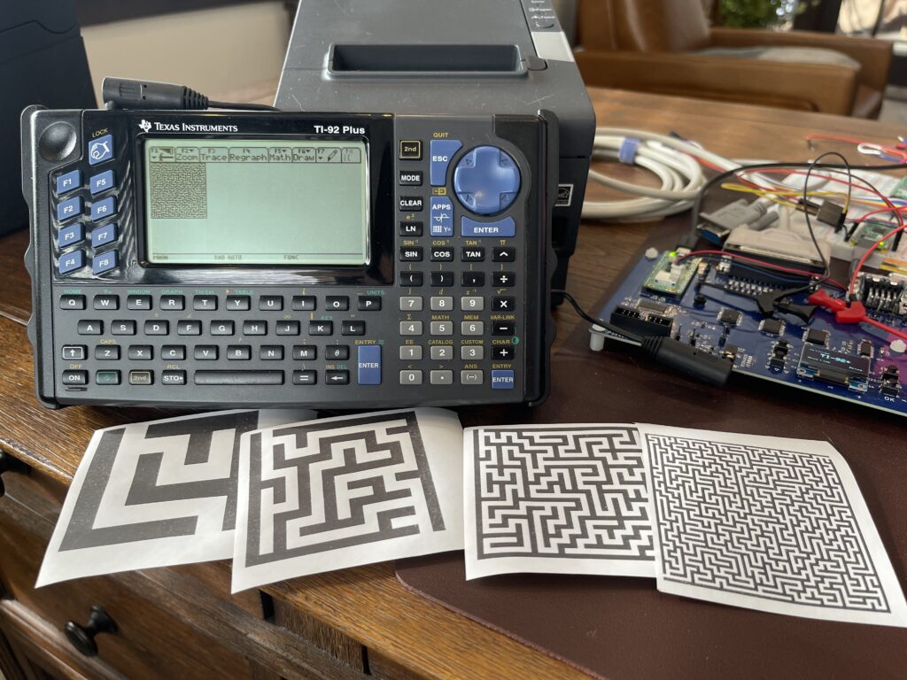
Since the TM-T88V receipt printer I had connected has a maximum pixel with of 512, the height values which fill most of the paper width are 7, 15, 31, and 63. The maximum width would be 240 pixels, making the largest maze possible 239 by 63 (for the given printer).
Due to the special characters the TI-92 uses for programming, for the maze program, I have embedded a PDF printout of the program below:
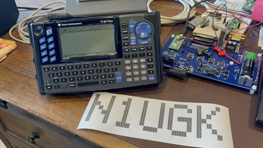
Banner Program
Since I was able to generate mazes with the TI-92 and print them (via the PCUI), I tried my hand at making a banner program for the TI-92, which is another program I write for various pocket computers.
Since the PCUI can receive variable names and their contents, I added a function in the PCUI to send anything it receives for a variable named “print” to the attached printer. If the variable is a string, then it sends the string to the printer as-is, and if the variable is an integer, it sends that to the printer as-is. This allows for the TI-92 to send not only ASCII characters but any control characters if needed, including carriage return and line feeds or perhaps ESC/POS commands.
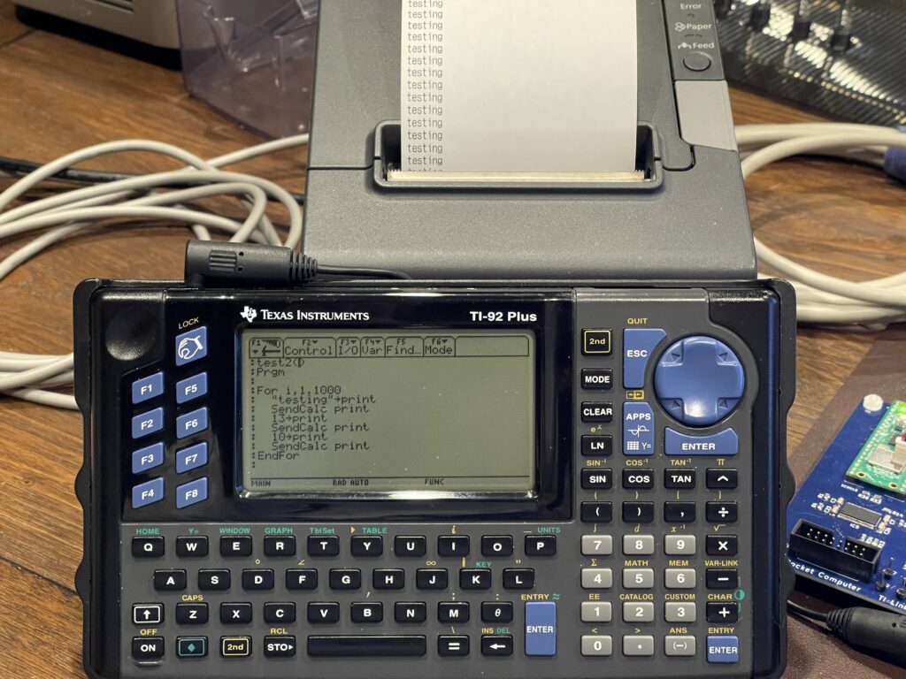
print - send data to the attached printer, can be a string or integerI wrote a short test program to demonstrate this functionality:
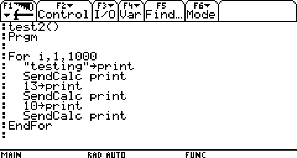
The result worked as expected, which allows me to print from a program as if the TI-92 supported a printer natively.
I would need some string manipulation functions for the banner program, and not being familiar with the TI-92 program functions available, I was able to find two functions that will be useful for the program: “dim” and “mid”. “Dim” returns the length of a string while “mid” returns any part of a string.
Since I do not have peek and poke capabilities directly from a built in function, I cannot use the built in font bitmap directly for banner printout. Instead, I can write a character to the screen and then detect pixel state for each pixel in that area of the screen.
I needed to use the PxlText function to draw the characters, one by one, on the display, then use PxlTest to detect each of the pixels in the 6 x 8 area. I then built a string of spaces and marks for each row in each of the characters. I then printed each row twice on the printer so that the expanded width matched the height for a more uniform aspect ratio.
Because I was testing with the Epson TM-T88V receipt printer, I leveraged its ability to redefine a character. I use this to define a solid block character, and I chose the “#” character to redefine to a solid block. My usual use of the tilde “~” character was not possible on the TI-92, since it did not have this character by itself in its character set.
I also set the line spacing to zero, to minimize the gap between rows when printed. And, at the end of the printout, the command to cut the paper is issued to the printer.
Since the PCUI can receive both a string variable and an integer variable, I was able to send both strings and specific byte values (for ESC/POS control sequences) to the printer.
The banner program accepts a string parameter which is the string to be printed as a banner:
banner("N1UGK")The printout was rather quick, surprisingly, given the chatty packet interfacing needed between the TI-92 and the PCUI.
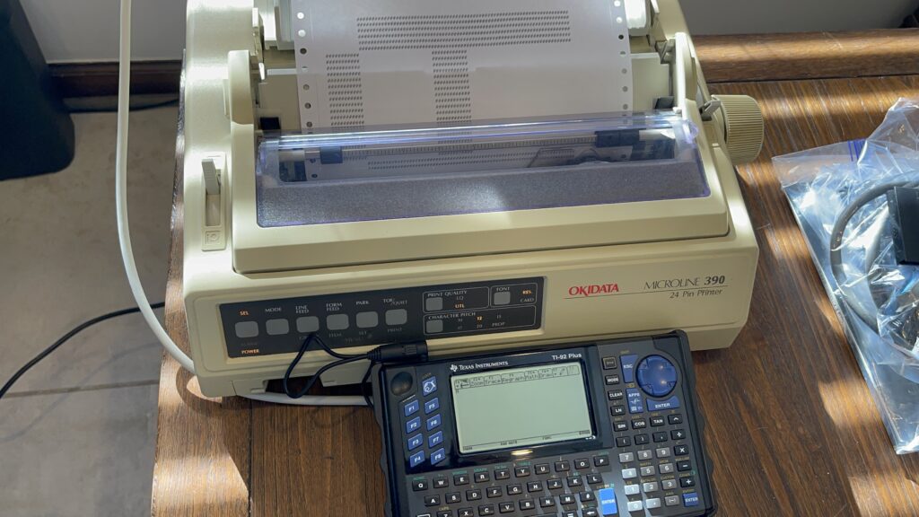
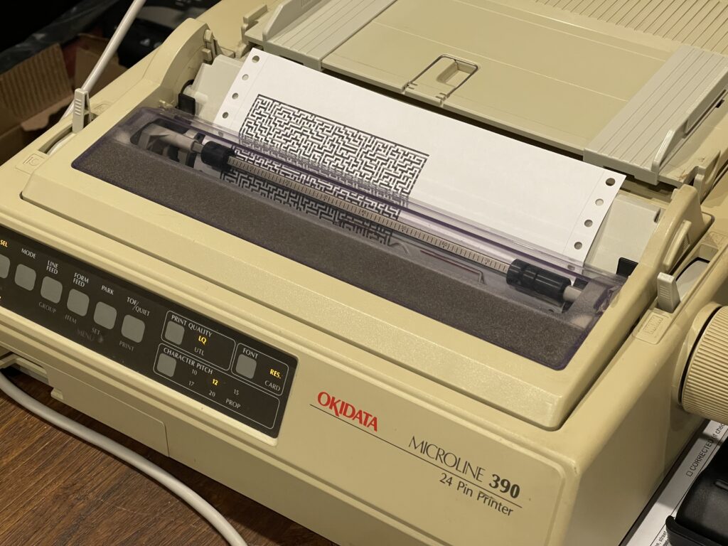
I connected an OkiData Microline 390 dot matrix printer to the PCUI and adjusted the settings in the banner program, and that also worked as expected:
Due to the special characters the TI-92 uses for programming, for the banner program, I have embedded a PDF printout of the program below:
Note that the settings for a large got matrix printer for the banner program should be: escpos=false, sclcol=12, sclrow=6, leadcol=0. The settings for the ESC-POS printers should be escpos=true, sclcol=5, sclrow=3, leadcol=8.
Voyage 200
The Voyage 200 was the successor to the TI-92 Plus, which added more Flash memory, 4MB instead of the 2MB on the TI-92 Plus.
The home screen is more “PDA” like, with icons for applications which are preinstalled.
Most of the applications for the TI-92 will run on the Voyage 200, and the basic programs will as well.
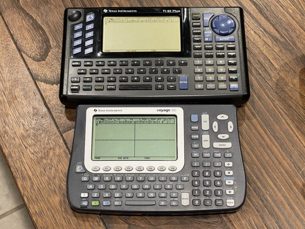
The Voyage 200 is a bit more compact, continues with the improved contrast LCD display, and has a slightly different keypad layout. The function keys have been moved to underneath the LCD. Further, the unit sits slightly elevated or angled upward a bit as opposed to completely flat on the TI-92.
Lastly, the batteries for the Voyage 200 are 4 “AAA” size and far easier to change than on the TI-92 Plus.
Larger Printouts
Using the Okidata ML 390 provides for larger printouts compared to a receipt printer. However, the printer is far slower and consumes ink in the form of a ribbon. The DPI is roughly the same as the Epson POS printers, but due to inexpensive knock off ribbons, the print quality is not as good as the thermal paper.
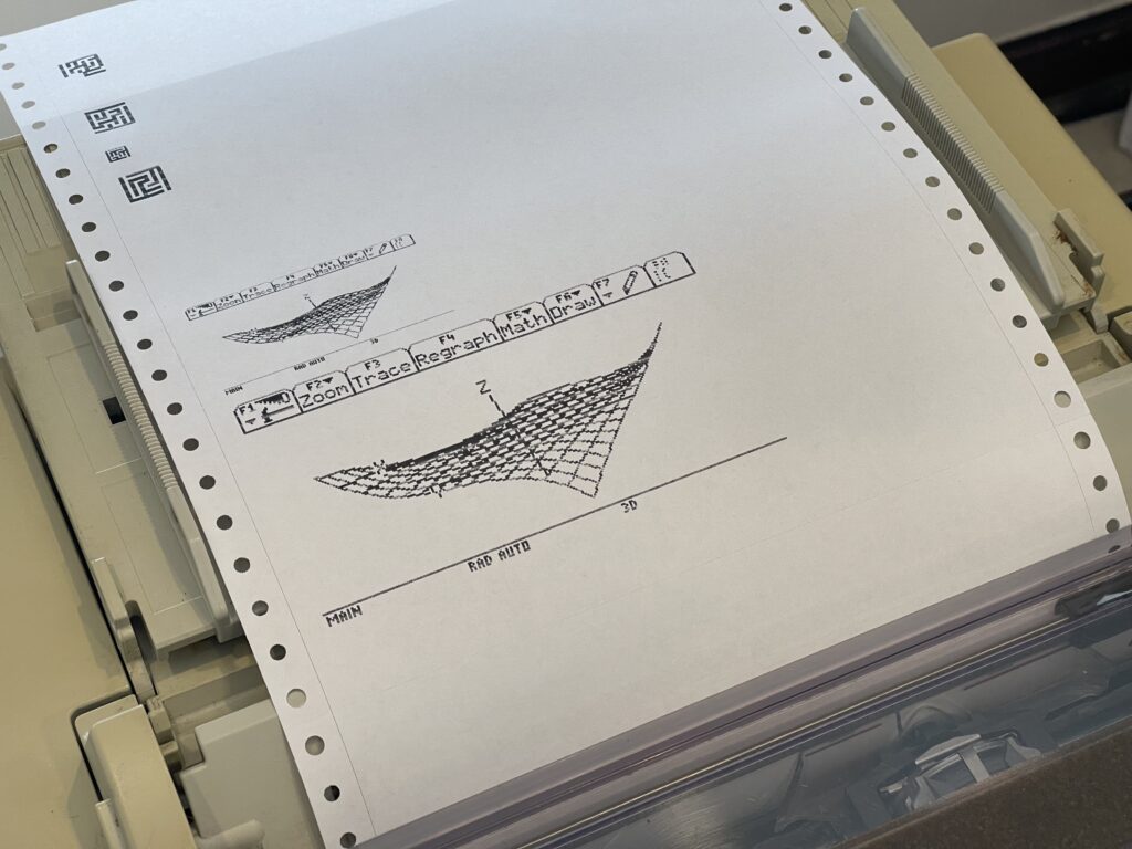
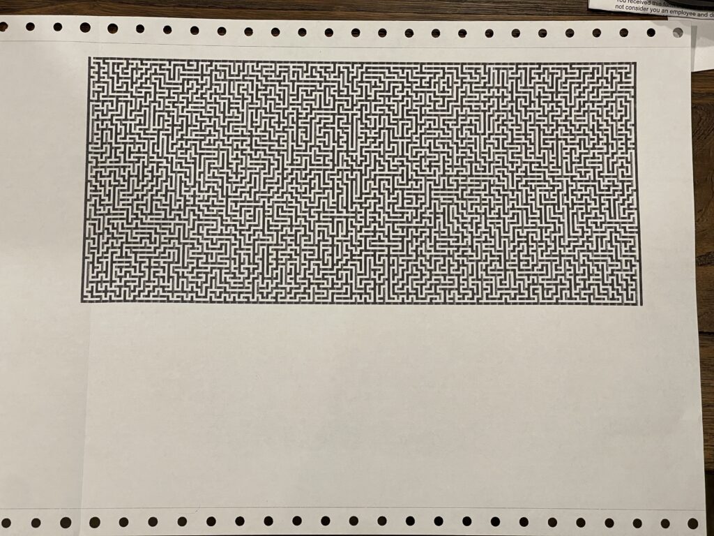
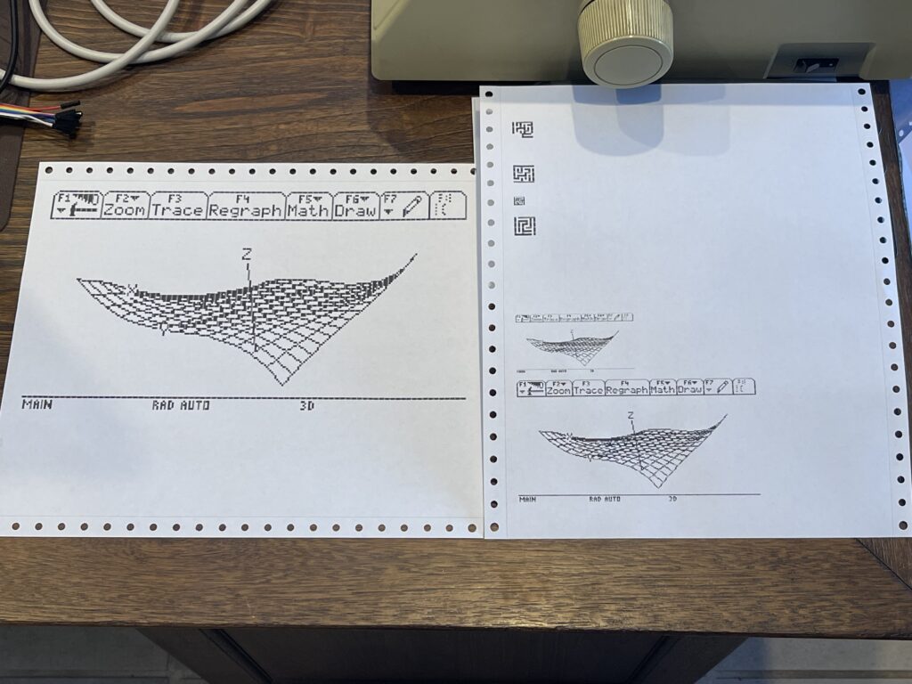
The larger printer canvas allows for the full screen maze output to be printed for example. I added support to rotate the image and scale, based on preference. These samples were printed using the same maze program on the Voyage 200.
The rendering speed is roughly the same as the TI-92 Plus and TI-92. This full screen maze took about an hour to render and another 10 minutes or so to print.
Below is a short video demonstration of the PCUI with a TI-92 Plus and a Voyage 200:
The PCUI, when attached to a TI graphing calculator, offers a web based view of the screen, which updates automatically:
In addition to the screen view, the PCUI accepts keyboard input on the page, allowing you to control the attached TI-92, TI-92+, and Voyage 200.
Final Thoughts
A few years ago I had wanted to get some assembly programs downloaded to my TI-85 and TI-86 and ended up purchasing a USB link cable from eBay. The cable was quite expensive, but it did work, and was necessary since my old gray link cable was not compatible with modern PCs. Of course, I could have used a USB RS-232 cable and a 25 pin to 9 pin adapter with the original gray link cable I had.
When searching for this USB graph link cable, I would see listings for TI-92s, which I had always wanted to get back in the late 90s, but were too expensive. Finding a bundle of them on eBay for a little over $10 each was quite a deal, and being able to repair them was rewarding.
Once they were repaired, I used the USB based link cable I had purchased, and I then began to think about writing a maze generator to familiarize myself with the programming capabilities of this model.
However, without a printer, I thought this would be a good addition to the PCUI project I was working on. If I added support to the PCUI for the TI graphing calculators (the old ones from the 90s), I could then use it as a graph link cable (in passthrough mode), I could print from within a program on the TI-92, and print screen shots on demand to whatever printer is connected to the PCUI.
There is quite a bit of documentation currently out there about the TI Link protocol, especially this site. I was glad to have been able to add printer support to these TI graphing calculators in a similar way the PCUI works with older Sharp, Casio, and Radio Shack pocket computers.
Of course this could be done via a PC or Mac and a graph link cable and the TI or TiLP software. In most cases, a PC or Mac does not provide printing, saving, and loading capabilities for the older pocket computers, so the PCUI fills that gap. Adding TI support makes it more useful for more models.
All of the features mentioned in this article for the TI-92 should also work with the other TI graphing calculators with a graph link port.
If you are reading this post and interested in the PCUI, reach out on the contact page.