

QRP Labs QDX Kit
The March 2023 edition of QST included an article on the QRP Labs QDX transceiver. For the past few months I have been experimenting with the (tr)uSDX with digital modes such as FT8 and JS8Call with an ultra portable PC.
Having had good results with QRP using the (tr)uSDX on these digital modes, when I ran across the article in QST on the QDX, I began to read up more on how it works. Not only would the QDX be a better rig for portable QRP operations on some digital modes compared to the (tr)uSDX, there are several unique properties of this transceiver compared to the other kits I have built.
In this article, I’ll explain what I find unique with this rig and why I chose to build the kit as well as my experience building and using it.
Single Tone Digital Modes
Throughout this article, the “digital modes” I am referring to are single tone digital modes such as FT8 (and its derivatives) and other modes which use only a single tone generated at any given time. Other modes which use multiple tones simultaneously will not work with the QDX.
When using digital modes with rigs in SSB mode, there is a process by which the SSB transceiver receives the analogue audio signal to be transmitted from the PC and transmits that audio signal via SSB modulation. If the input is a single tone, that single tone might not be as pure is it can be, or, it may have a sub optimal level. Depending on the transceiver, factors such as AGC, ALC, audio gain, and noise from the input source may cause sub optimal output. For example, I had some issues with audio noise when connecting my PC directly to the (tr)uSDX.
Innovative Approach by the QDX
Depending on how the SSB transceiver is designed, transmitting a single tone via SSB modulation might not be as efficient as transmitting the same signal by directly sending a synthesized sine wave to an RF power amplifier. In some cases, the signal may not be as pure if transmitted via SSB modulation. For example, the (tr)uSDX outputs a much cleaner signal on CW mode than it does with the same tone in SSB mode.
The QDX is unique in that it samples the incoming tone(s) from the PC and detects the frequency of the tone. It then synthesizes that same tone as a pure sine wave and sends it to the RF power amplifier. The result is a very pure output signal at high efficiency.
Further, the audio level of the output tone from the PC does not affect the RF output signal on the QDX. Because the QDX samples the source signal and synthesizes the output signal, the audio level needs to be at a minimum level that the QDX can sample the frequency from. This means that you do not need to adjust or fine tune the volume output from the PC, nor do you have to keep an eye on the ALC level as you would with an SSB rig. The QDX needs a minimum level of audio input for sampling and a higher level of input does not affect the output.
QDX Options
QRP Labs offer the kit or pre-assembled versions and an HF or HF high bands option. The HF option is 80, 60, 40, 30, and 20 meters, while the HF high bands option is 20, 17, 15, 11, and 10 meters.
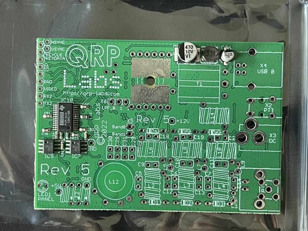
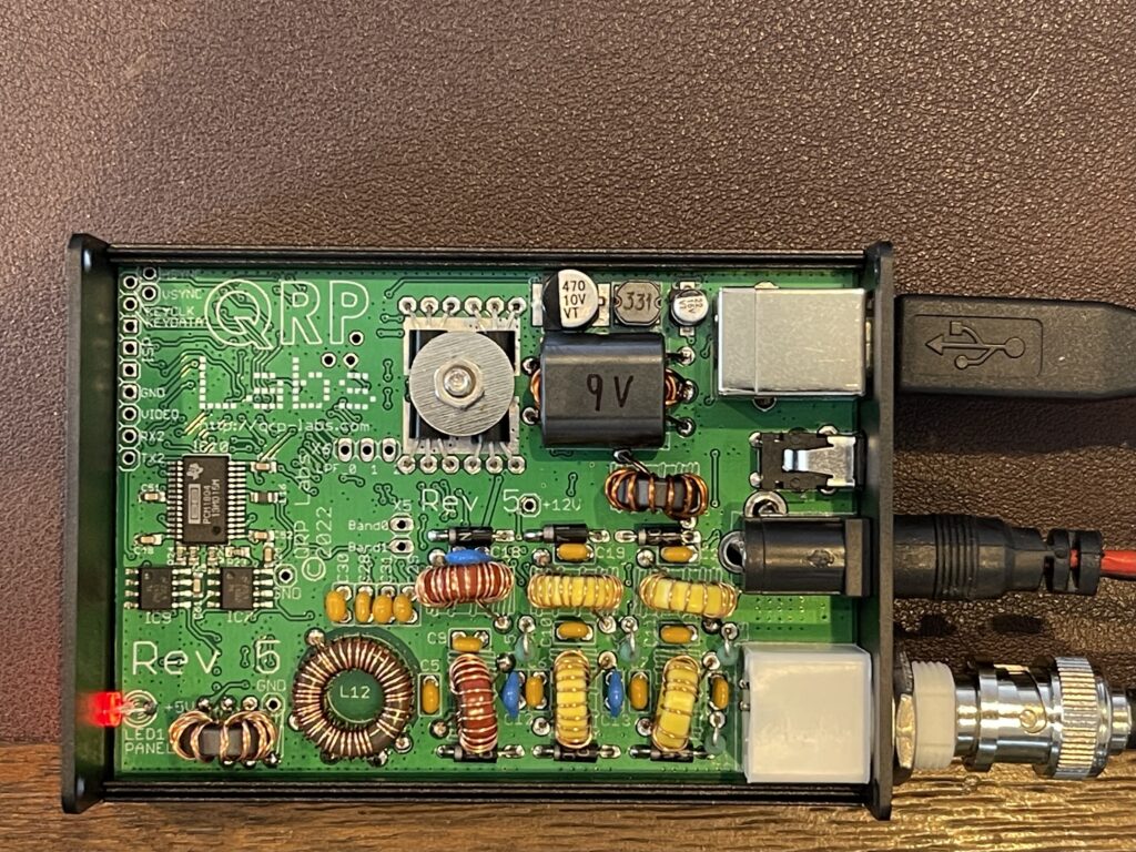
I chose the HF option and the kit with the enclosure. I would rate this kit as one that would take an experienced kit builder to complete. Due to the small PCB size and the toroid winding involved (T2), a beginner or first time kit builder might find this kit a challenge to build.
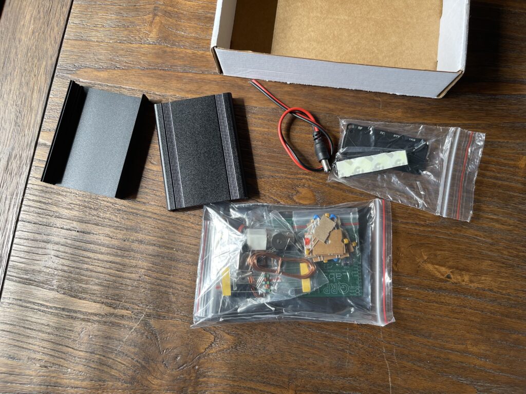
As with the WSPR and (tr)uSDX kits, I would highly recommend the enclosure or case. Anything that has toroids or static sensitive parts can be easily damaged if not enclosed in a case. This is especially true if you plan to use this portable. There was the option to include the DC supply barrel connector, which I chose to do. I would have liked to have had a connector which had heavier gauge wire for adding a Powerpole connector. You might want to source a connector or cable elsewhere.
Assembly Guide
The assembly guide is excellent. It includes pictures of the most detailed assembly steps. Since there are not as many build decisions as the WSPR kit, the assembly of this was a bit easier in many ways.
9 Volts or 12 Volts
This kit did not have many build decisions to make, but there is a choice you will need to make for the supply voltage. The most important build decision to choose is whether you wish to run the QDX from a 9 volt or 12 volt supply.
The number of turns for transformer T1 depends on whether you wish to run the QDX on 9 volts or 12 volts. Since the QDX is an ultra portable digital mode transceiver, I wanted to build it with my most likely source of power in mind, which is a LiFePO4 battery. Since that power source can vary between 12.8 volts and a little over 14 volts (if being charged), I would be placing the QDX onto my smaller 12 volt Powerpole distribution block if I chose to build it for a 12 volt source. I use an 18-12 volt DC to 12 volt DC voltage regulator from my main Powerpole distribution block to a smaller Powerpole distribution block for devices which I want to run at no more than 12 volts.
The QDX assembly guide includes a graph illustrating the output power versus supply voltage for 9 volts and 12 volts:
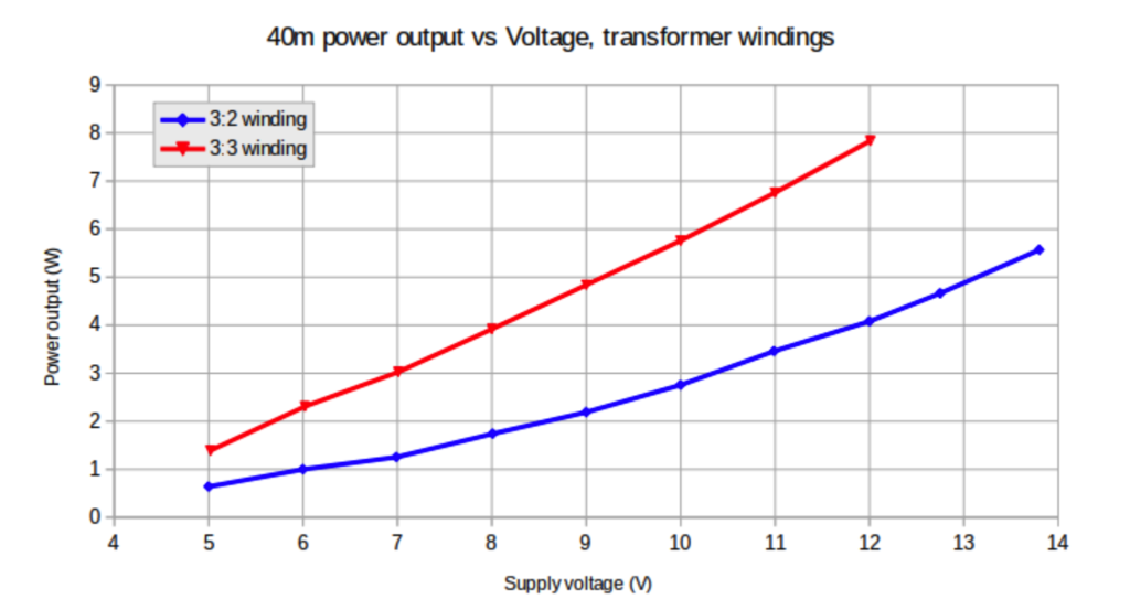
Since I would be using a 12 volt DC regulator from the power supply into the QDX if built it for 12 volts, I figure I might as well build the QDX for a 9 volt supply and use a 12 volt to 9 volt DC regulator. These can handle 15 or more volts (roughly) and keep the output at a steady 9 volts. I can then connect this 9 volt regulator to my main Powerpole block, or, directly to any other supply 12 volts or higher if I wanted.
According to the chart above, if I were to connect the QDX to a LiFePO4 battery, then the output would be about 4.75 watts (assuming a 12.8 volt battery voltage) compared to a 5 watt output at 9 volts. If building for a 12 volt supply, feeding 13.8 volts or 14 directly into the QDX to approach the 5 watt output would not be advisable. In summary, it would be more of a challenge to find a steady voltage source to obtain a 5 watt output if built for 12 volts.
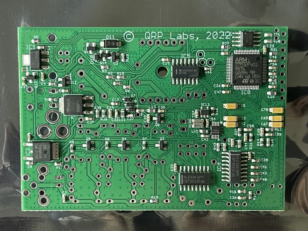
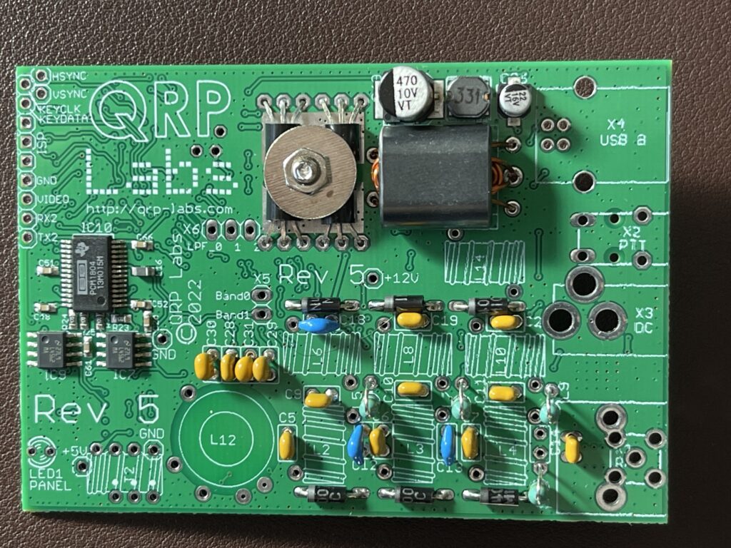
T1 is a binocular toroid, and this is the first kit I have built which has a binocular toroid.
Tapped Inductor
L12 is a 41 turn inductor with multiple tapped points, which are switched by the QDX depending on the operating band. This is the first kit which I have built which has multiple tapped points on a single inductor. I triple checked the windings and tap points.
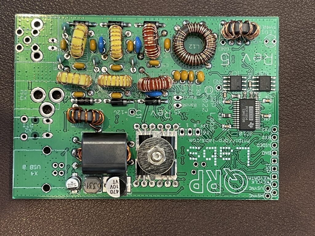
I made a few minor mistakes with this kit. The first was incorrectly soldering in C14 to the BNC connection area. The second was accidentally breaking some of the 28 AWG magnet wire when winding the trifilar toroid T2. Luckily I had some left over wire from a previous kit.
Because of the small 28 gauge wire used on the multi-tapped toroid and other toroids, testing continuity where described in the assembly guide is critical. I’ve had to touch up a few places with the soldering iron to melt away the enamel. With the larger gauge magnet wire, I prefer to scrape off the enamel rather than use heat.
Power Cable
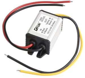
I decided to use Powerpole connectors for the power cable so that I can easily run the QDX at the QTH or portable. Since I decided on a 9 volt operating voltage (as opposed to 12 volts), I purchased a 12 volt to 9 volt buck converter (about $14 on Amazon). This allows me to be able to power the QDX from a source between 12 volts and 14+ volts while keeping the input voltage to the QDX at a steady 9 volts.
Since the barrel connector that came with the kit was not easily attachable to a Powerpole connector, I soldered some heavier gauge wire to that connector, then added Powerpole connectors to that section of wire. I then added Powerpole connectors on each side of the 12 volt to 9 volt buck converter, and another Powerpole extension cable for connection to a 12 – 14 volt source.
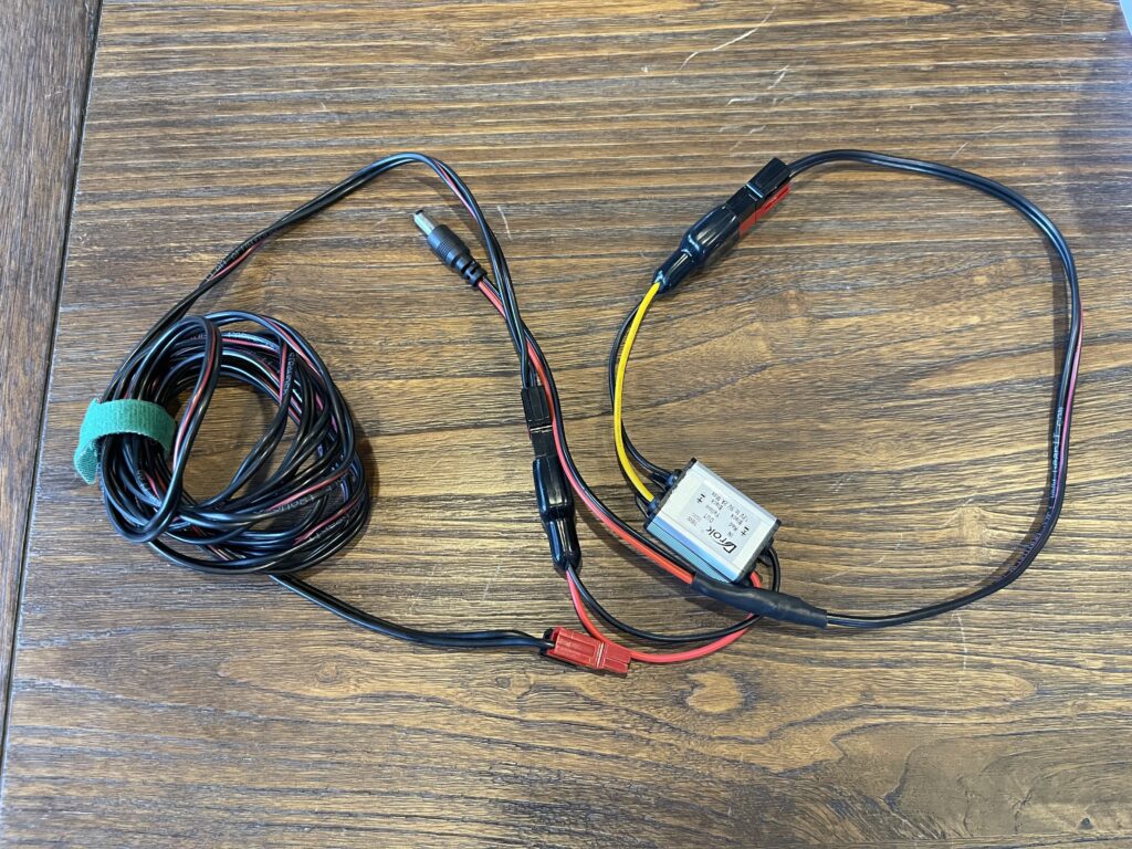
This might seem a bit over complicated, but I prefer to be able to reuse pieces of these types of cables for different rigs or modes when needed. This allows me to adjust the length of the wire, reuse the voltage converter for other purposes, etc.
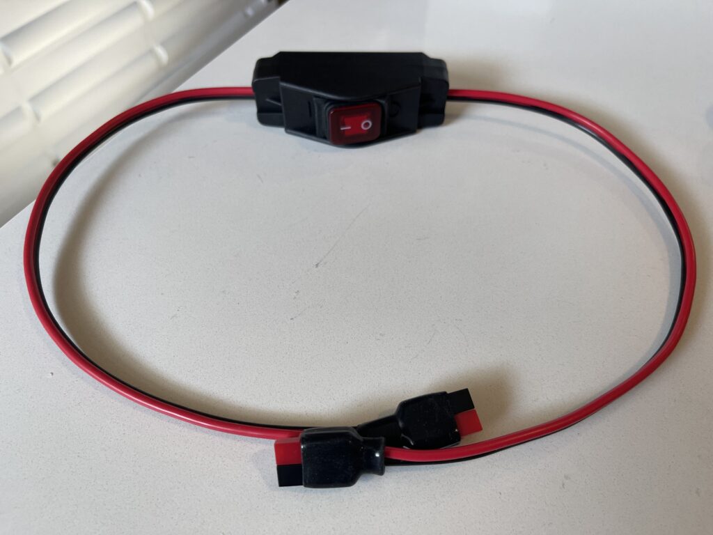
It should be noted that there is no power switch on the QDX at the time of the writing of this article. I made a switch with Powerpole connectors on each end that I can add inline to this cable assembly. I don’t want to wear out the DC plug or Powerpole connectors by unplugging the rig each time I’m finished using it.
Smoke Test
After assembly, I powered up the QDX and it worked! I plugged the USB cable into the PC and the new COM port and sound devices appeared as expected. Further, using PuTTY (a terminal emulator), I was able to run the diagnostics in the service menu.
Output Power Tests
I tested the output power on all bands using the service menu which has a transmit test tone feature. I ran the BNC RF output into a 50 ohm dummy load and connected a scope across the dummy load.
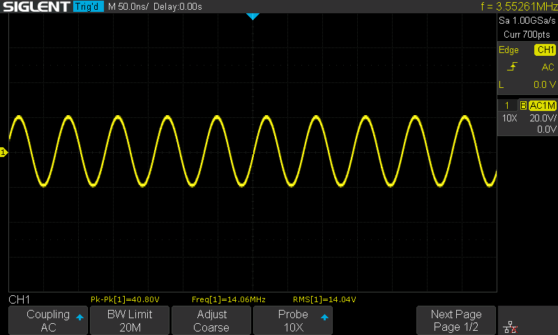
The following are the measured output power levels for each band using a 9 volt supply:
| Band | Measured Output |
| 80 Meters | 5.95 Watts |
| 60 Meters | 7.02 Watts |
| 40 Meters | 5.06 Watts |
| 30 Meters | 5.42 Watts |
| 20 Meters | 3.65 Watts |
RF Filter Sweeps
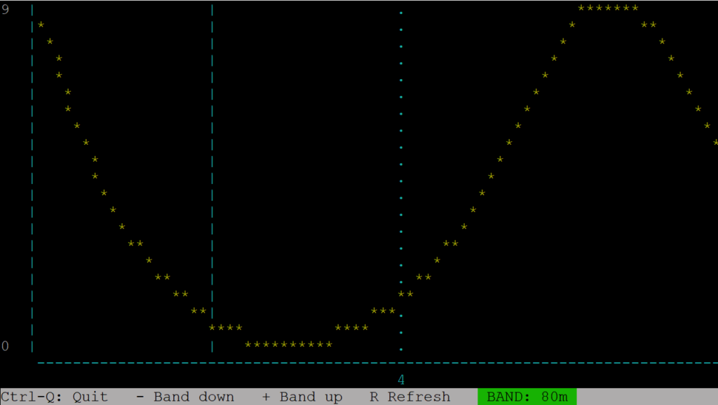
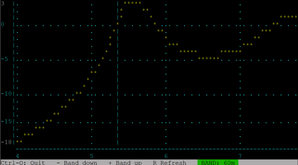
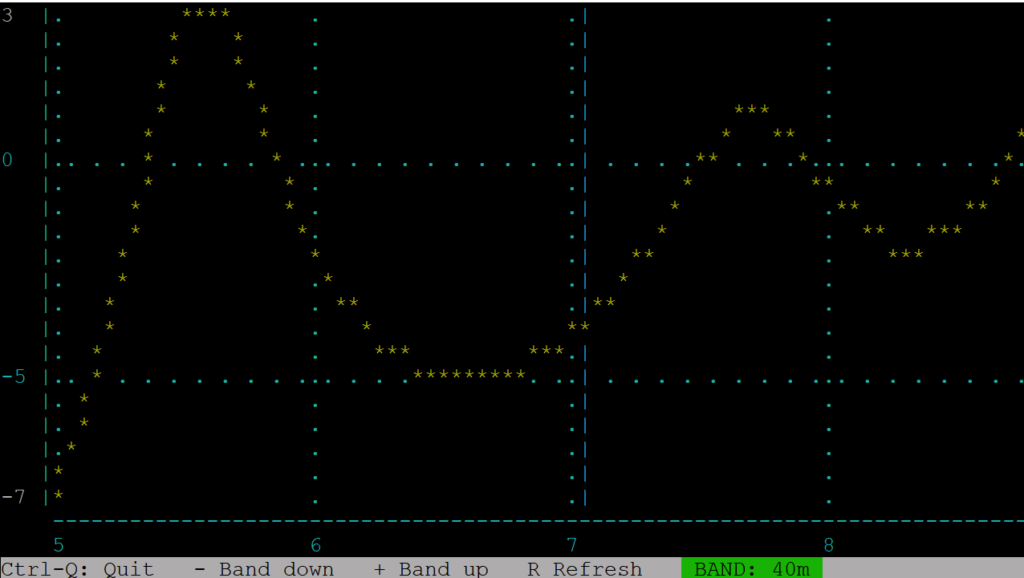
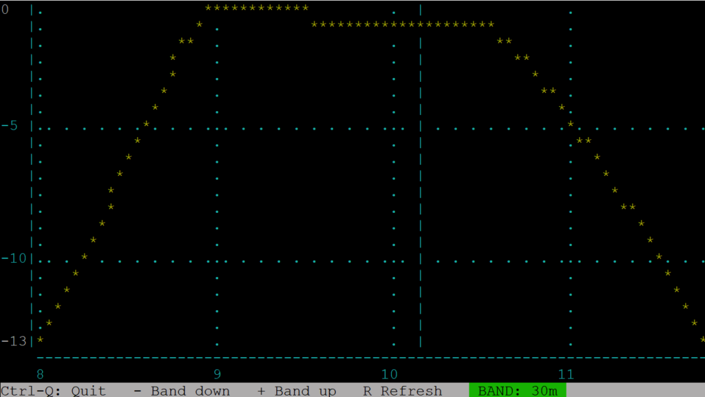
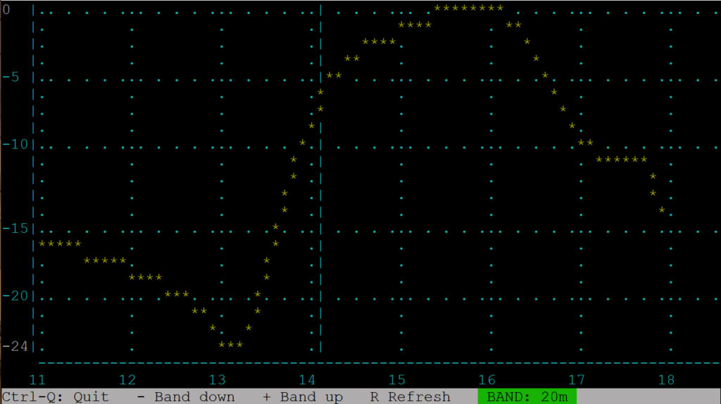
The RF filter sweeps look at the receiver bandpass filter. I ran the RF filter sweeps for all 5 bands. The windings on L12 (the multiple tapped toroid) might need adjusting depending on the results of the sweeps.
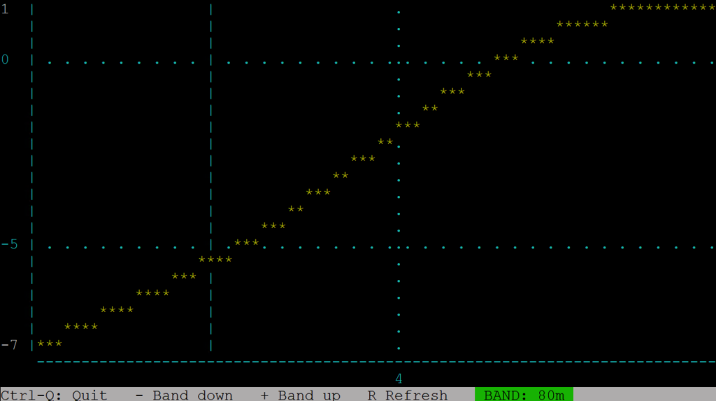
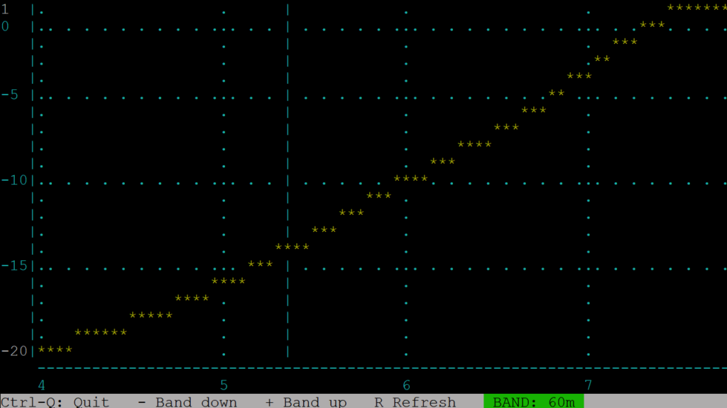
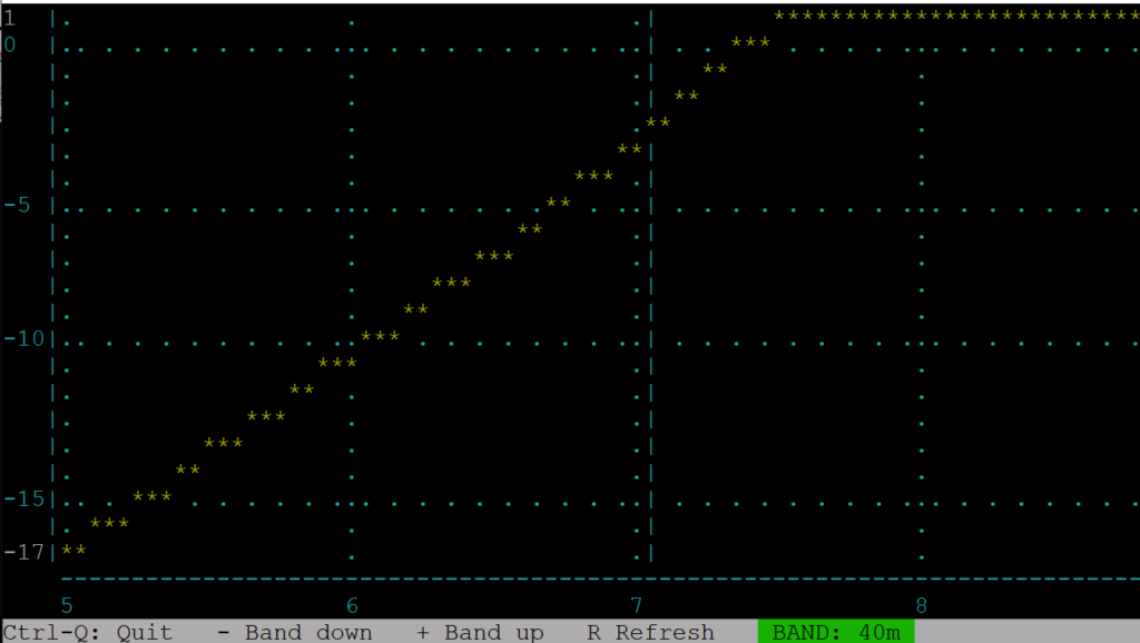
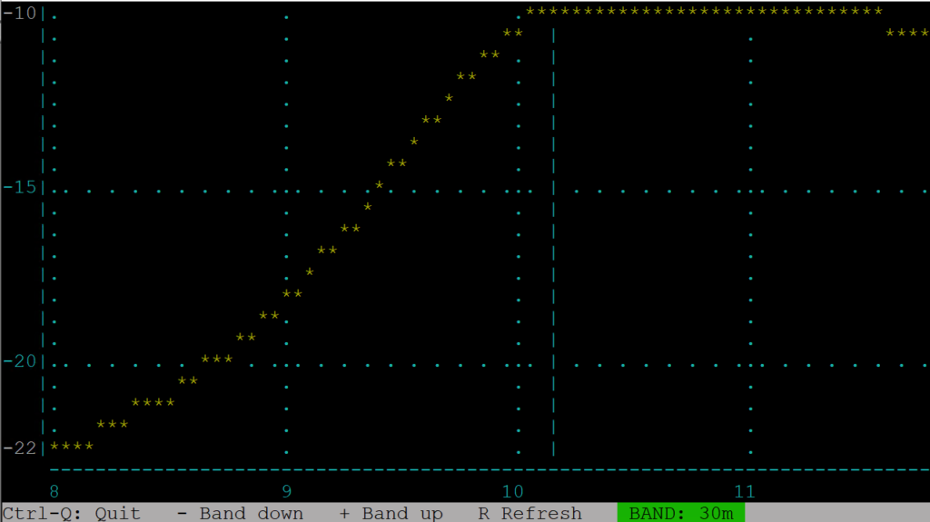

The blue dotted vertical line indicates the default transmitting frequency for the band, which is listed in the band configuration screen (usually the FT8 frequency). The Y axis is the audio level in decibels, the X axis is the frequency. The minimum and maximum audio level is shown in white on the Y axis.
The results for 60 m looked a bit off, having the FT8 frequency in the band at almost a -12db level. The 30 m band also had interesting results, the maximum audio level was at -10db.
Since L12 is part of the receiver bandpass filter, I’m not certain how much impact these measurements have on actual receive performance of the transceiver.
I tried tweaked the spacing a bit on the windings on L12 to make them a bit more evenly spread around the toroid and made my measurements again, and found different results:
It appears that I had improved the 30m and 60m bands but have odd visual results on 80m and 40m.
A day later, I reran the sweeps and they were back to the previous results (without anything touched on the QDX). The only difference between the two measurements was time of day. The first set taken in the morning, the second in the afternoon. The next day, in the morning, the sweeps looked like they did the previous morning.
I decided to leave the winding spacing alone after seeing that there was little to no change on the RF sweeps.
On Air Testing
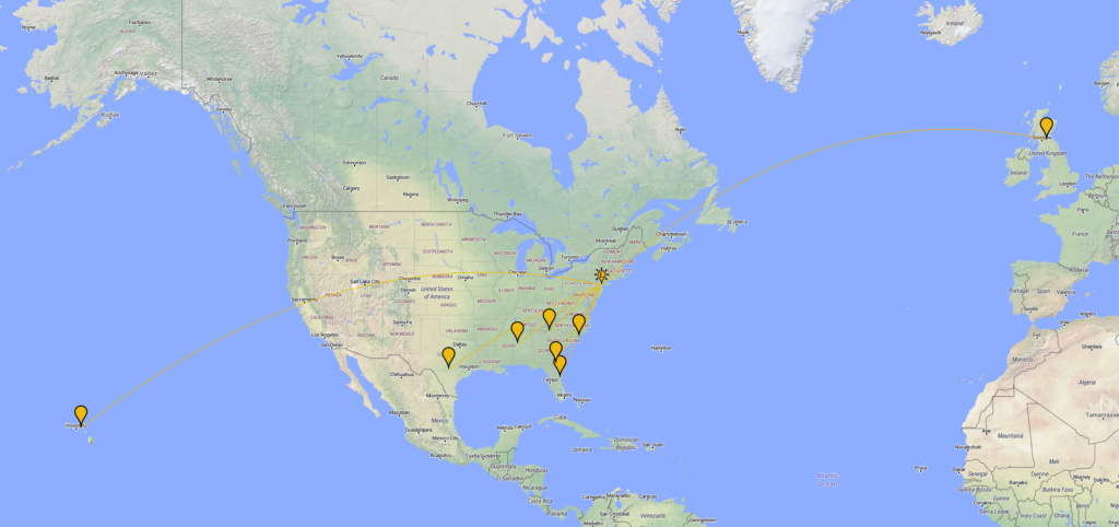
I tested the QDX on 20 meters using JS8Call and FT8 for several days. The initial results were as expected, with farthest stations reporting from Europe and Hawaii for JS8Call:
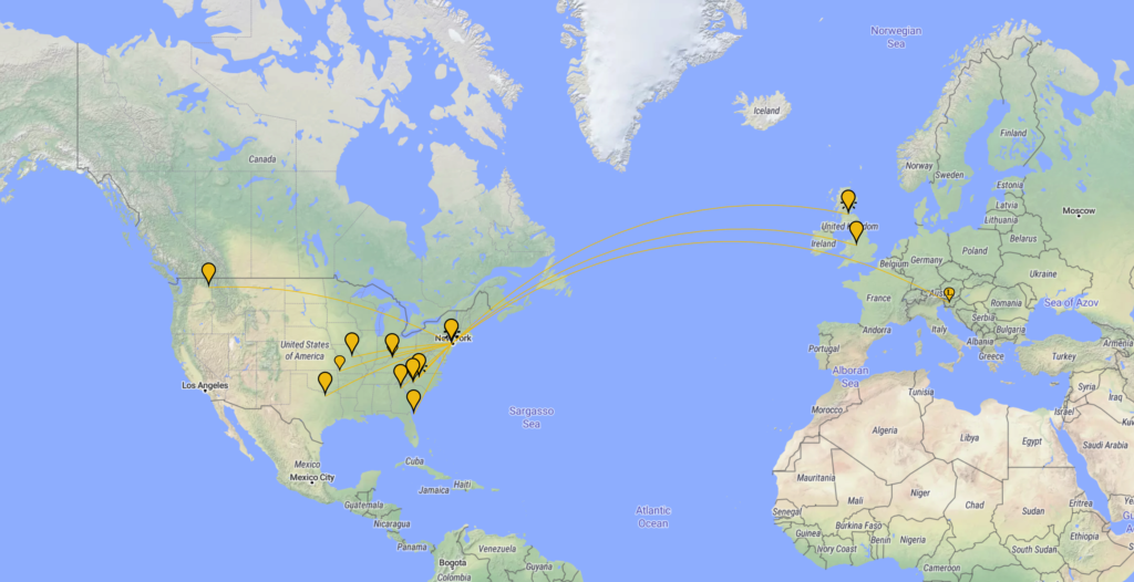
FT8 testing on 20 meters was great, with stations hearing me from South Africa, Europe, and western U.S.:
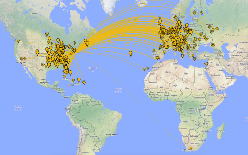
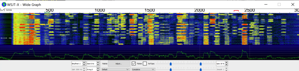
Receive tests on FT8 were excellent. I heard the farthest stations from South Africa, the Middle East and Europe. The WSJT-X waterfall indicated nearly packed 20 meter FT8 activity:
All tests were performed in the late afternoon on an OCFD.
Frequency Stability
Since the QDX is designed for digital modes, it would need to have a relatively accurate and stable VFO . I use the word “relatively” because you can also do digital modes with older transceivers including hybrid rigs which do not have TCXOs (temperature controlled crystal oscillator). These VFOs were accurate enough for many of these digital modes and there is some frequency tolerance within the specifications for these digital modes. The QDX has a TCXO and therefore the frequency drift should be minimal to none. The specification for this particular TCXO is +/- 5 Hz for the 25 MHz output setting. At 20 meters, this translates into +/- 2.8 Hz.
I was thinking about using WSPR to determine the accuracy of the transmitter’s VFO. However, I noticed the reporting was not very accurate for many stations. I transmitted a WSPR signal at 1,500 Hz, which at 20 meters would be a frequency of 14,097,100 Hz. Below is the result of 2 transmitting intervals:
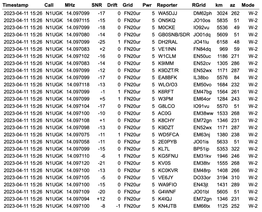

The drift reported by these stations was mostly 0 Hz, with a few 1 Hz offsets here and there. Since the QDX has a TCXO, drift is not a concern. Since the specification for the TCXO is about +/- 3 Hz at 20 meters, this indicates many of the receiving stations are quite a bit off.
QRP Labs offer a web page which can be used to determine your WSPR offset in Hz from a standard 1,500 Hz WSPR frequency on the 20 meter band. Simply transmit a WSPR cycle on 20 meters at 1,500 Hz, and the page will indicate your offset. Mine was exactly zero – spot on.
Firmware Updates
Updating the firmware on the QDX is a simple process without the need to use a programming cable. To update the firmware, the QDX can present itself as a removable drive and the firmware can be placed onto the drive for the QDX to use for the update process.
Final Comments
The QDX is an innovative QRP rig for many of the popular digital modes. Due to the small size of the transceiver and excellent performance, this kit will no doubt be my go to rig for FT8 and JS8Call for QRP. This kit would also be the perfect transceiver for an off-grid emergency communicator, using JS8Call and an ultra mobile PC. I may pick up the HF high bands version since we’re on the upswing of the solar cycle. Even though this transceiver is limited to single tone digital modes such FT8 and it’s derivatives and RTTY, it makes an excellent choice for POTA or emergency communications.
QRP Labs have a groups.io forum for their kits, should you have any questions or issues.