


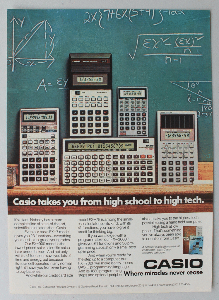
Casio FX-702P Programmable Calculator
The Casio FX-702P was released in 1981, about one year after Sharp released their first BASIC programmable pocket computer, the PC-1210. The PC-1211, the successor to the PC-1210 had increased memory. I suppose the FX-702P can be considered the competitor to the Sharp PC-1210 and the PC-1211, which is the same as the Radio Shack TRS-80 PC-1.
The Sharp PC-1210 would be the first of many models that would follow with more memory, better printers, and peripherals. Similarly, this model, the Casio FX-702P would be the first of many other Casio models with similar advancements over time.
As with many of the pocket computers not sold by Radio Shack, it is difficult to determine exact availability here in the United States, if this model was ever directly sold here at all.
Some previous Casio models were programmable, but had a typical calculator form factor and did not support BASIC. This model would be the first to not only support BASIC programming, but it was the first Casio model to have the familiar landscape form factor typical of pocket computers which would be released after this one.
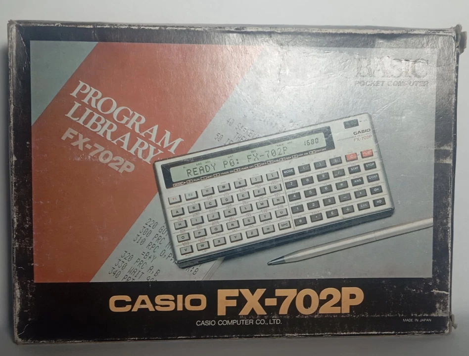
The box for the FX-702P is interesting in that it highlights BASIC and that this model is a “pocket computer”, even though the badge on the computer itself and elsewhere on the box it has the “Programmable Calculator” labelling as many of the previous models did.
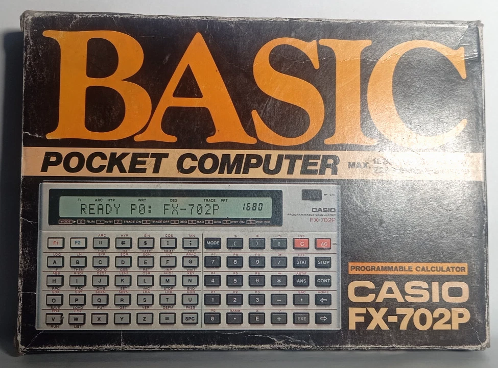
Future models were labelled “Personal Computer”. Perhaps this was the point where their marketing shifted away from describing the models as calculators and more like computers.
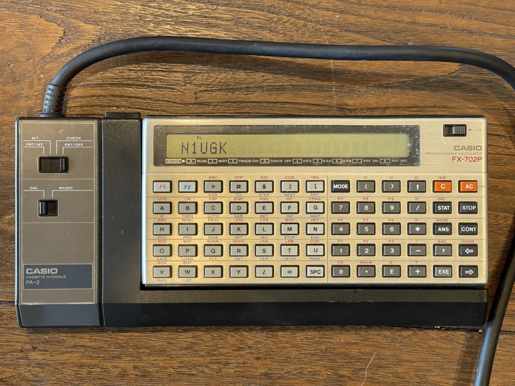
Screen and Keyboard
The screen is a 20-character LCD which is not dot addressable. The font is a 5 x 7 character set and individual indicators are above the alpha numeric section for the mode(s) and status. This model has only upper case characters.
There is a contrast wheel on the top which is useful for adjusting the display angle.
Unlike the Sharp PC-1211 (and the TRS-80 PC-1), the LCD does not appear to suffer from leakage over time, for the most part. This makes the FX-702P more readily useable these days without requiring an LCD replacement.
The keyboard has dedicated numeric and operand functions for simple calculations, making this model easy to operate as a simple calculator.
The character keys, on the other hand, are not laid out in a “qwerty” arrangement, which takes a bit of getting used to. The Tandy PC-7 (also a Casio model) had a similar arrangement.
The keys themselves are made of plastic, not rubber, adding to the durability of this model.
There is no buzzer on this model, which is unfortunate, since the competitor, Sharp included one on their PC-1211 model.
Batteries
The FX-702P uses two CR-2032 button cell batteries, which is typical for pocket computers. These batteries ended up becoming more common than the mercury based batteries that the Sharp PC-1211 used.
Memory
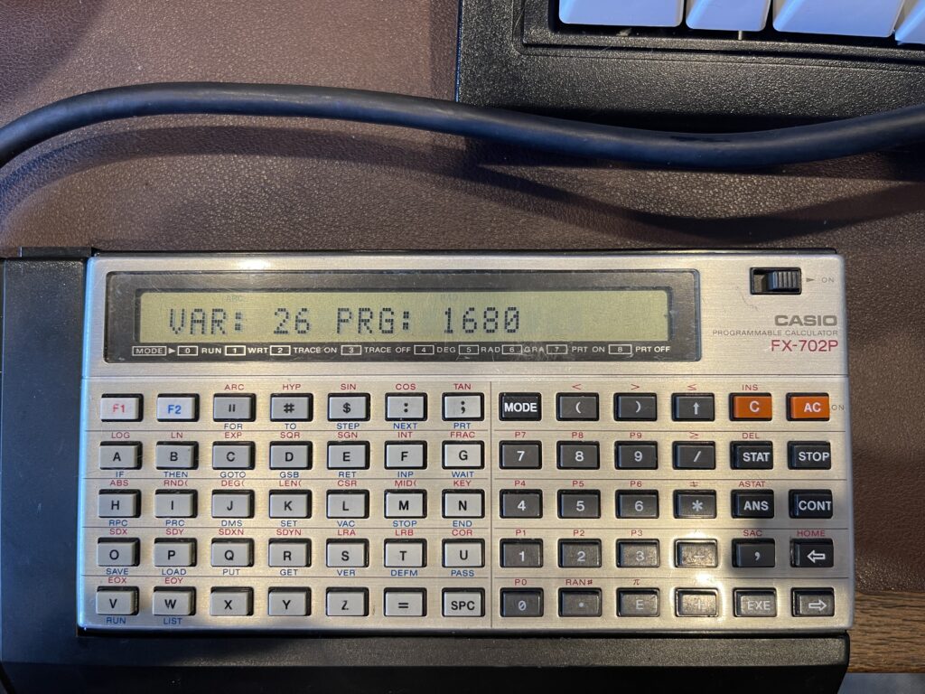
The memory is segmented into “steps” and variable space, similar to the Sharp PC-1211. By default, there are 26 variables and 1680 steps.
Memory can be allocated away from the steps and made available for additional variable space using the DEFM statement.
The program space is segmented into ten program areas, P0 through P9, similar to future Casio models.
Mysterious Expansion Slot
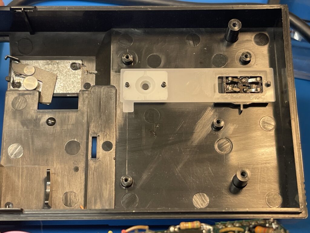
The back cover is easily removable, exposing the battery compartment and a mysterious expansion connection:
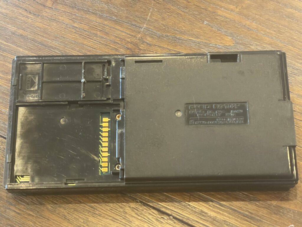
I have not been able to find any reference to any ROM or RAM expansions for this model. Perhaps Casio added this when they developed the model, but never developed or released any ROMs or RAM expansion packs for it. As of the time of the writing of this post, there are no known aftermarket add-ons using this expansion connection.
Acquiring an FX-702P
I did not specifically look for an FX-702P, but one came with a bundle of pocket computers I had acquired when looking for the Casio PB-2000C.
The unit I acquired is fairly used, with some light scratches and wear over the LCD window. It is in average shape, but not heavily banged up. Mine did not come with the soft case nor any manuals. It did however come with the FA-2 cassette interface.
The owner’s manual for the FX-702P is below:
The service manual for the FX-702P is below:
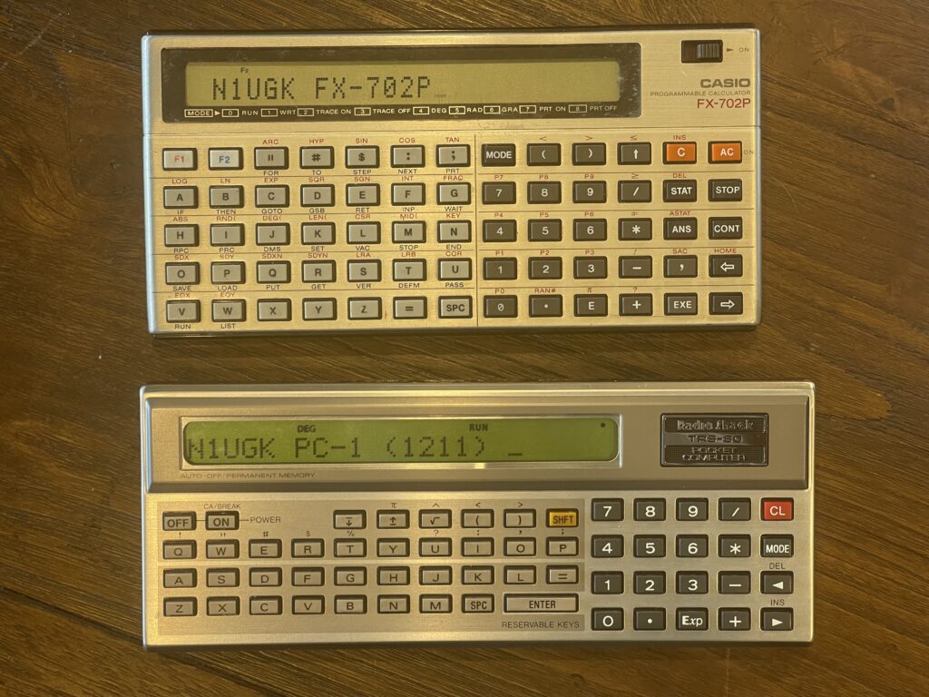
The FX-702P was released before the PB-100 series and the FX-700P (which had the same form factor as the PB-100 series). The comparison in size and shape of the FX-702P and Sharp PC-1211 (TRS-80 PC-1) are pictured below:
Interface Port
The FX-702P has an interface port on the left side, which is a proprietary 7-pin connection:
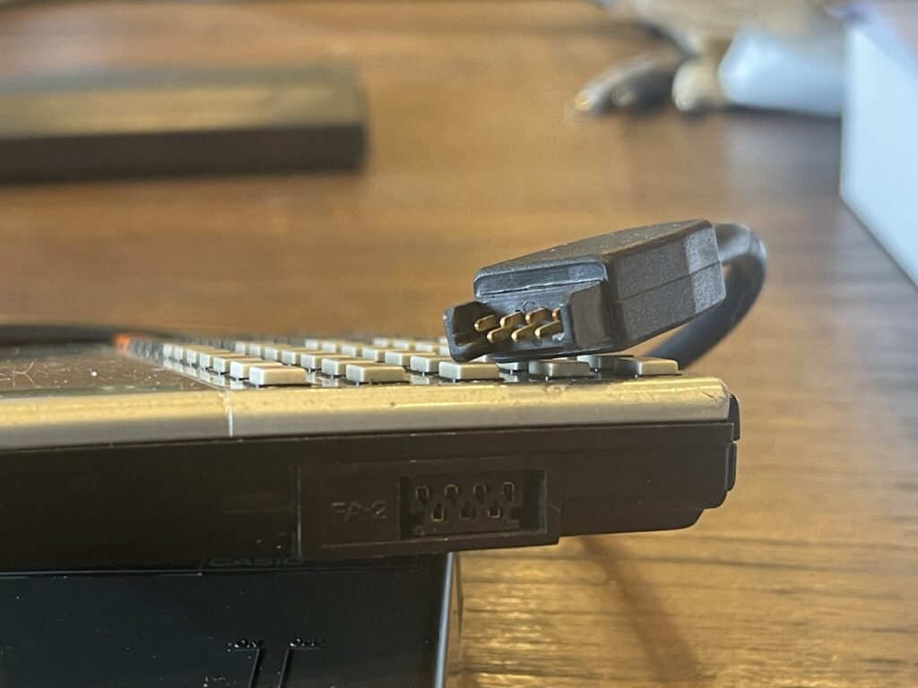
The port is keyed to prevent reverse connections, and is labelled “FA-2” on the FX-702P. The corresponding connector for the FP-10 printer is shown as well. This is the same port as the FX-602P, and the peripherals for the FX-702P are compatible with the FX-602P.
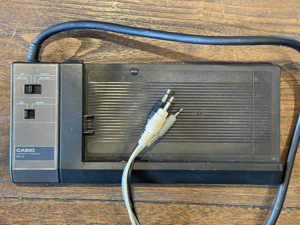
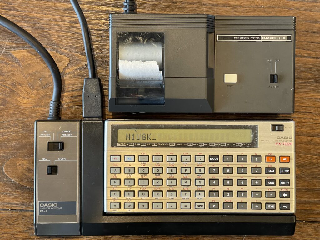
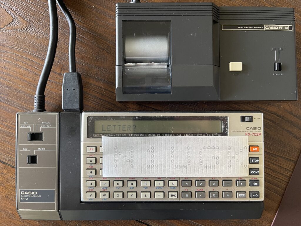
FA-2 Cassette Interface
The cassette interface designed for the FX-702P is the FA-2. The FX-702P fits into the cassette interface similar to the Sharp PC-1211. The FA-2 will also work with the FX-502P and FX-602P, which is why there is a CAL/MUSIC switch on the FA-2. They can generate music in the form of variable notes (pitch) and duration, and then output the result through the FA-2 connected to an amplifier. There is no such feature on the FX-702P.
The music feature was not described in the owners manual for the FX-502P nor FX-602P, it was described in the FA-2 manual. The FA-2 also came with an overlay sheet to be used with these models for music generating features.
The other switch allows for independent control of the tape circuit and printer connection. The FP-10 printer can be connected via the port on the top of the FA-2:
Interestingly, the FA-2’s microphone, speaker, and remote wiring is not removable from the FA-2 itself, much like the PC-4’s and PC-6’s cassette interface. For example, on other Casio cassette interfaces such as the FA-10, and Sharp’s CE-150, the tape connectors can be unplugged from the module itself, when not in use.
The FA-2 requires 3 “AA” size batteries. Interestingly, mine came with a vintage “Eveready” brand battery stuck inside. I noticed this when I attempted to load some Amazon Basics “AA” batteries. I had not seen one of these since the early 1980’s and I was surprised that it did not leak.
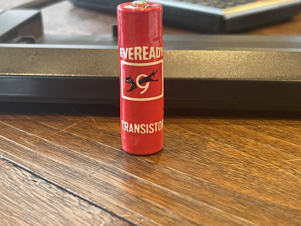
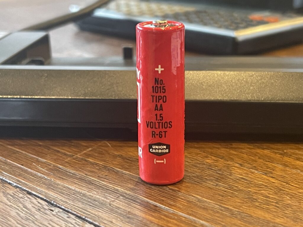
Due to the language on the markings on the battery, I can assume the FX-702P and FA-2 were not likely used here in the United States.
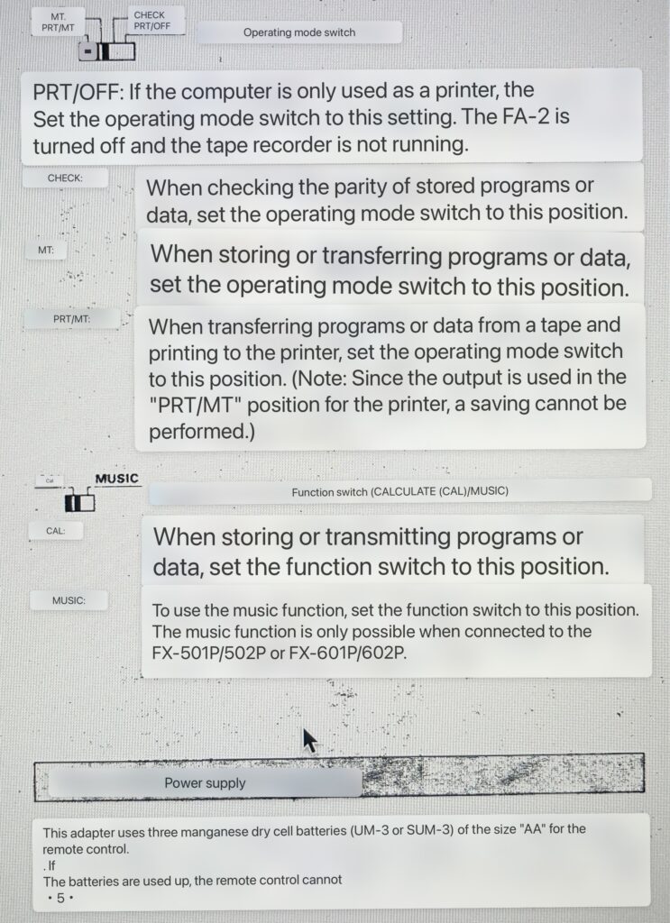
Curious about the various switch positions and their functions, I was able to find a German version of the FA-2 manual, and used the iPhone to translate this section of the manual:
I have included the German FA-2 owners manual:
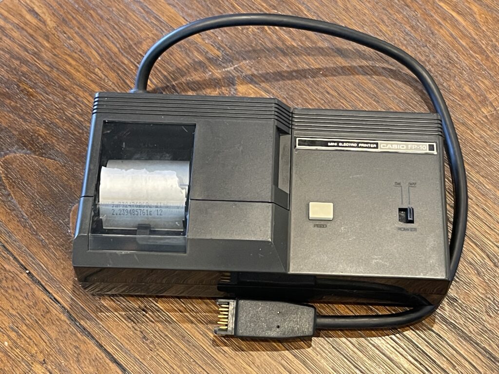
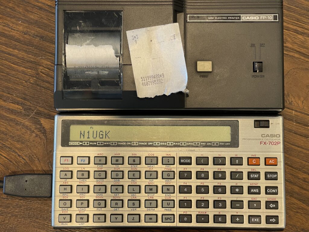
FP-10 Printer
The compatible printer for the FX-702P is the FP-10 printer. This printer is quite unique from all of the other pocket computer printers I have used or have experience with. Up until this point, I have printers that are dot matrix (impact), thermal, and plotters (using pens). The FP-10 is a spark printer, branded as a “Mini Electro Printer”. It boasts a 20 character line width and a speed of two lines per second.
The FA-10 is not only compatible with the FX-702P, it also works with the FX-501P, FX-502P, FX-601P, FX-602P and the FX-9000P.
Spark (electrostatic) printers were an inexpensive alternative to other options at the time. This type of printer was also used by Sinclair for the ZX Spectrum, by Radio Shack for the Quick Printer and Quick Printer II, and for some Casio printing calculators to name a few possibly familiar uses. This being my first spark printer, I had absolutely no idea exactly how they worked, nor what to look for when attempting to get one working 45+ years after they have been manufactured.
All of the spark printers work similarly. They require a special type of paper which is similar to thermal paper. The paper required for spark printers is a black paper with a one-micron aluminum coating over it. There are electrodes on the print head which burn away the aluminum on the surface of the paper, exposing the black color underneath. The “spark” is the visible effect of the current flow burning off the aluminum layer between the paper surface and the electrode(s) on the print head.
Similar to dot-matrix and thermal printers, the number of electrodes and density of those electrodes determine the print resolution of the printer. For example, to print a font which is 7 pixels high, 7 electrodes would be needed in order to print a single line with one pass of the print head.
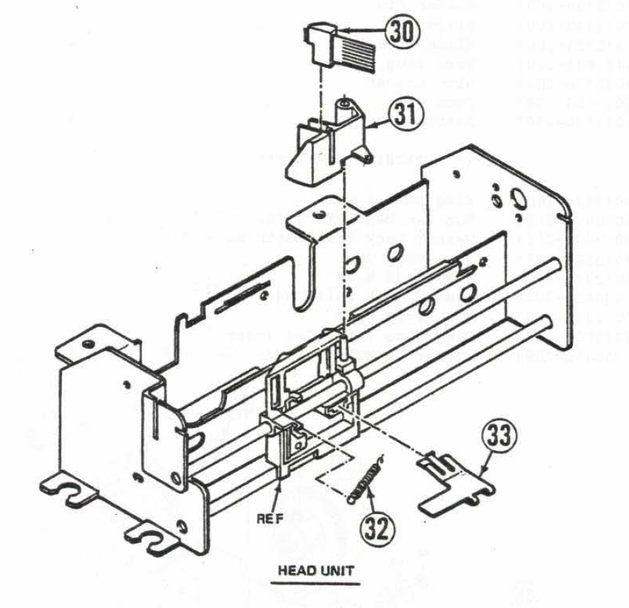
In the image above, the print head with electrodes is at the very top, indicated by number 30.
Interestingly, in the user guide, at the very end, in the FCC information area, there is reference to the FX-702P being connected to the FP-10 printer, “on sale in the near future”. I had thought the FP-10 had already been released by the time the FX-702P was released, assuming it was used for the FX-602P originally.
The FX-602P manual makes no mention of the FP-10 printer whatsoever. The FP-10 manual (French version as my source) mentions the 601P/602P as being compatible with the printer. I suspect these models output the display contents to the expansion port automatically. This could also be why the FA-2 cassette interface has a switch position for “MT” – if the printer were connected to the 601P/602P via the FA-2, then you can switch off the printer without unplugging the printer. On the FX-702P and many other Casio models which followed, a MODE 7/MODE 8 command controls printing (or LPRINT vs PRINT).
From the French user guide, for using the FA-2 with the FX-601P:
When the connection is made through the FA-2, the mode selector of the latter must be placed on “PRT/OFF** when only the printer is used, and on “PRT/MT” when you want to charge from a tape recorder and print at the same time.
Another interesting finding was the inside of the FP-10 seemed to have supported a physical switch activated by a battery pack being put into the battery compartment. In the French version of the FP-10 manual (I could not find an English version), there is mention of a rechargeable battery pack, the NP-4M.
I have included the French version of the FP-10 owners manual:
Finding an FP-10
The FP-10, like most other pocket computer printers, is not as common to find as the PC-2 (Sharp PC-1500) plotter. Once in awhile these will pop up on eBay and other sites. A saved search came up with an alert on an FP-10 for $44 USD, plus shipping. However, like almost everything I pick up from eBay and other sites, it was sold “as is” with no returns. Due to the lack of supply of paper for these printers, I did not want to spend all that much on one of these printers.
The printer does not have an internal NiCd pack (thankfully), unless the previous owner(s) left “AA” batteries in the unit, battery leakage was not likely. The unit takes 4 “AA” batteries or an external power supply.
When the printer arrived, it came with a partial roll of paper. I loaded 4 “AA” batteries in, took the cover off the top to check the paper roll, connected it to the FX-702P, and tried to print out a simple calculation. The print head moved, the paper advanced, but nothing printed. I repeated the test a few times with the same result. I did not expect the printer to work without at least some troubleshooting, but was a bit disappointed that it did not work.
Troubleshooting the FP-10
As this is the first spark printer I have ever seen or used, I was not familiar with exactly how they work. For example, if this were a dot matrix impact printer, like with the PC-1, I would check the ribbon and lubricate the pins if there was no print output to the paper. If it were a plotter, like with the PC-2 or Casio FA-10, I would check the pen(s) and check the pinion gears.
I took a slow motion video of the printer in action, specifically the print head to see if I could spot any sparks when viewing the video, and saw nothing. I had assumed at this point that there was no current or not enough current on the electrodes for removal of the aluminum coating on the paper.
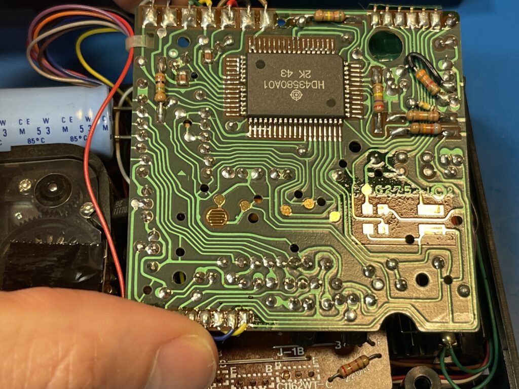
I took apart the printer and examined the electrolytic capacitors for signs of leakage or failure and nothing looked out of the ordinary.
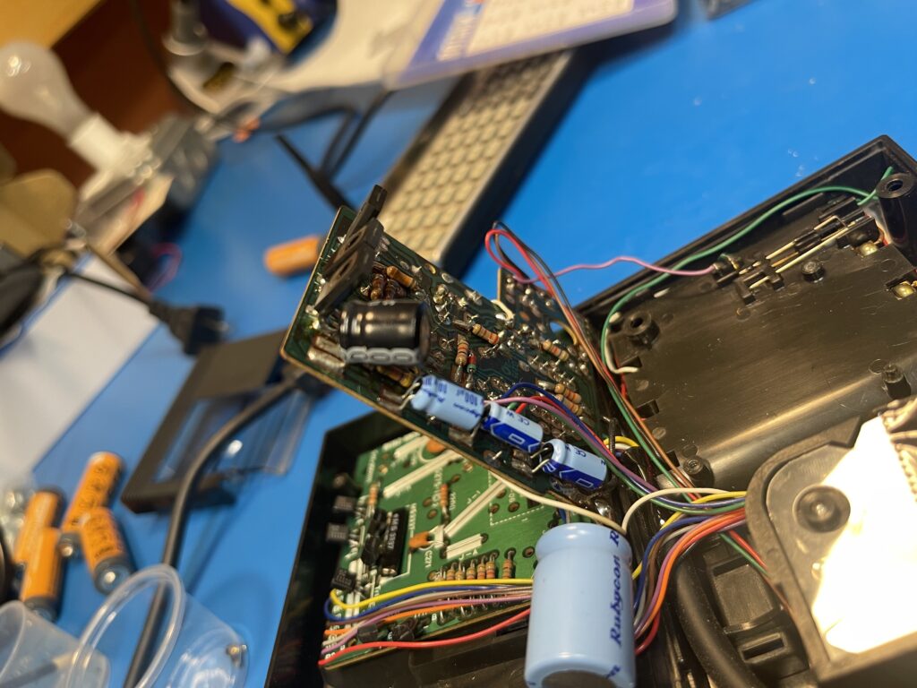
I then attempted to measure the voltages on the ribbon cable leading to the print head with a scope. I did not see any high voltage pulses on any of the pins, but did see a lower voltage than I had expected. At this point I had assumed that one of the electrolytic capacitors might be failing, and I tested them all in-circuit with an ESR tester. They all passed.
I then took note of each of the maximum voltages on the capacitors, and the highest voltage rating was 50 volts. I then replaced all of them with functional equivalents, tested the printout again, and no spark.
I noticed the power switch had multiple contacts and thought that it might be possible that one of the contact points was not being switched. This could explain the motor working but no spark. I cleaned the power switch contacts with DeoxIT D5 and checked the contact points with an ohm meter to ensure contacts were being switched correctly. Nothing was wrong with the power switch.
At this point in the troubleshooting, I would need to trace the electrode circuit all the way back as necessary to see where the failure was. I did find a schematic online which would be helpful in tracing out the parts of the circuits needed for troubleshooting in depth:
Before I started any in-depth probing of this printer, I did some basic research on how these printers work. I started with the Centronics Quick Printer manual from 1978 as a source:
This happens to be the same printer as the Radio Shack Quick Printer, as Radio Shack rebadged and sold this for the TRS-80 line of computers.
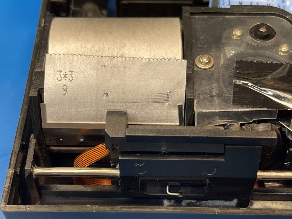
The voltage output from the electrodes on the print head is only approximately -34 volts at 12 mA. Further, the paper itself is about 1 ohm resistance as seen by the electrode(s). At this relatively low voltage, a spark is not going to occur between the distance I saw between the print head from the paper. I then reviewed the slow motion video I captured of the print head movement on the FP-10 and noticed the mechanism moves the print head toward the paper, as if it is physically in contact with the paper, then it moves the print head back away from the paper when it rests.
Suddenly it became obvious to me why the printer was not printing. In order to see any sparks from the printing process, I definitely need the aluminum coated paper loaded, and I need the print head to be in contact with the paper. In fact, the manual for the Centronics spark printer mentions uneven wear on the bottom electrode(s) due to underlining and extended length characters not commonly printed compared to the higher positions on the print head. It mentions using a fine grit sand paper to sand the lower two electrodes down a bit so that they make even contact with the paper. The electrodes are made from stiff wire tungsten.
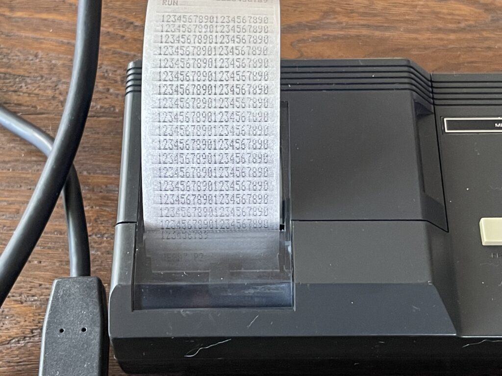
I loaded the paper and placed the cover on and tried a printout – it worked!
Perhaps the capacitors never needed to be changed, but, I certainly now know how these spark printers work, and how important the paper and print head positioning is. Sparks definitely will not be visible unless the paper is loaded and the print head contacts the paper when printing a line.
The quality of the printout is quite impressive. It has high contrast and surprising precision when compared to the thermal printers for the PC-4, PC-5, PC-6 and PC-8 as a comparison.
I suppose the early thermal printers for pocket computers had more “bleedover” to adjacent pixels compared to the spark method this printer uses. A close up picture below illustrates the precision and lack of “bleedover” effect that early thermal printers exhibited:
Replacement Paper
Since these spark printers were from the late 70’s and early 80’s, and better technology has replaced them, finding paper for them today is difficult. I have yet to find newly manufactured aluminum coated paper of any size, let alone the 35mm paper width needed for this model. Thermal paper most definitely does not work, as there is no electrical path for the current to flow from the electrodes when using thermal paper.
The Radio Shack Quick Printer used 4.75″ wide aluminum coated paper. This is just over 120mm wide, which is just over 3 times wider than the 35mm wide paper that the FP-10 uses. In theory, I could use this paper as well, if I cut it, which would divide up by 3. The Quick Printer II used 2 3/8″ wide aluminum coated paper, which is just over 60mm wide. This paper is not wide enough to divide into two, but would certainly work if cut down to size.
Another source of paper is from Obsolete Radionics, which lists paper width of 60mm.
As luck would have it, I happened to find a few roles of the Radio Shack Quick Printer II paper on eBay for a decent price. I could use this paper by cutting the width down as needed.
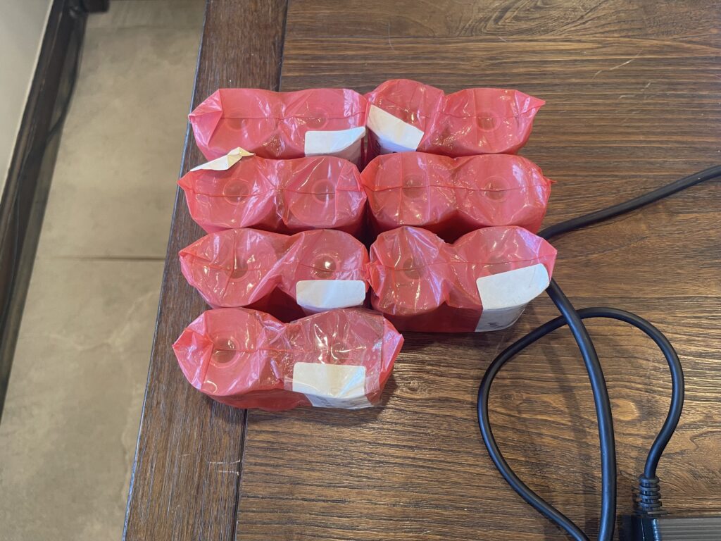
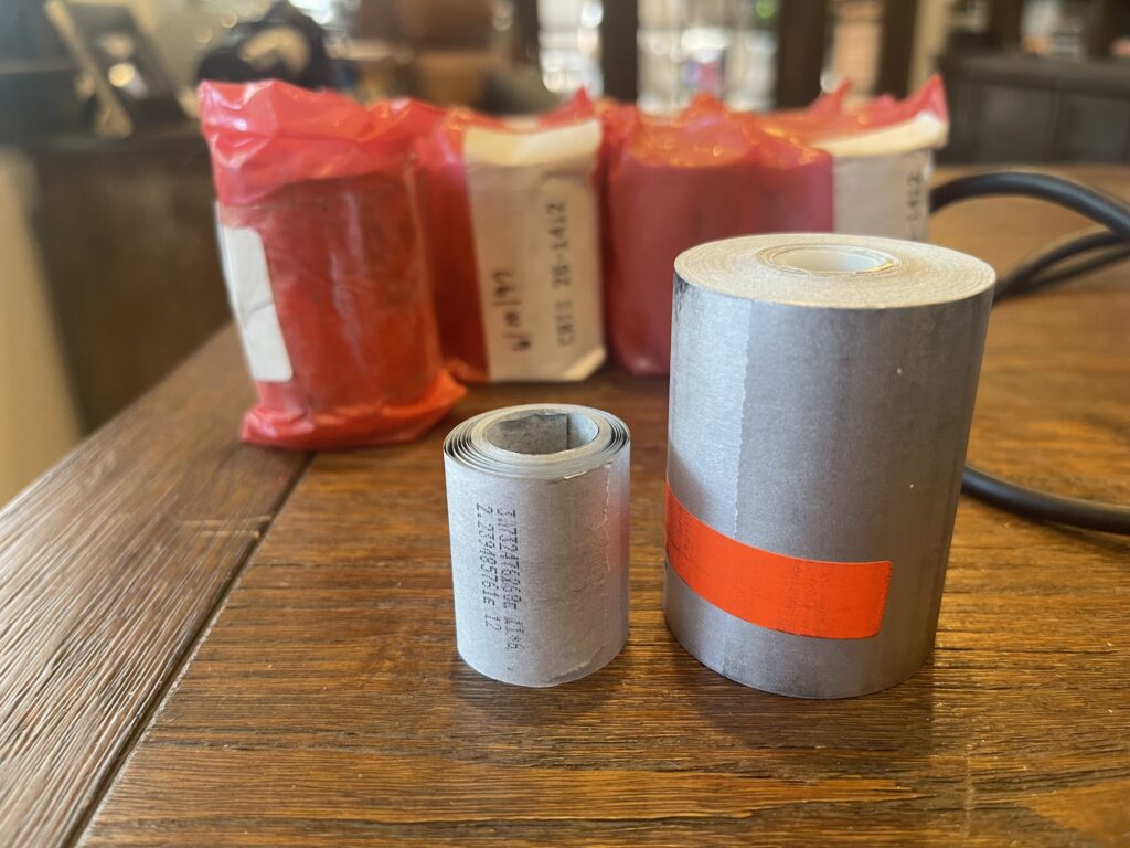
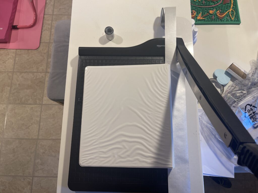
This paper is 60mm wide, and needs to be cut to 35mm. I ended up using a paper cutter to cut the paper width down to 35mm. I was able to easily cut about 15 feet by moving about a foot at a time through the paper cutter, and coiling up the result as I went along:
The paper is also a bit thicker than the paper which was designed for the FP-10, so the printer electrodes are a bit closer to the surface of the paper, and they leave a slight mark when printing:
There is no adjustment for the printer head nor electrode distance to the paper, and the mechanism has a spring that pushes the print head forward so that it touches the paper.
Banner Program
My banner program is the benchmark I use to learn the capabilities of each of the pocket computer models and their printers. For some models, this is more challenging due to lower memory available, fewer BASIC commands available, and/or quirks with the printer that need workarounds.
For some pocket computers, I can pull the font bitmap data directly from the ROM, while for others, I need to include it as part of the program. For the FX-702P, I need to include the font bitmap data in the program itself, as the ROM is not accessible and the bitmap data is likely within the LCD controllers themselves.
Since I had successfully created a version of the banner program for both the PC-1 and PC-4, I am already experienced with addressing the limitations with workarounds for limited memory and limited BASIC commands available. The FX-702P has just 26 variable spaces and 1,680 steps for programs. Memory can be pulled from steps to increase variable space. Similar to the PC-1 and PC-4, this model does not support DATA, READ, and RESTORE. This means the font data would need to be stored in variable space as opposed to program space, which can be far less efficient.
When working with the PC-1 and PC-4 (the “A” version), which also does not support DATA, READ, and RESTORE, I was able to pack all of the font bitmap data into 46 variable locations. Similar to the PC-1 and PC-4, there are 26 pre-allocated variables on the FX-702P, A – Z or A$ – Z$. If you need more than these 26 locations, the DEFM statement can be used to expand this beyond the 26 built-in locations. However, variables beyond the 26 built-in locations will consume the same memory space as programs would.
There is a special variable, $, which can hold up to 30 characters. This variable is needed in order to map user input for letters or characters to the corresponding location in the font bitmap data. This is necessary because there is no character to ASCII code conversion command or vice versa in the FX-702P. This also means I cannot easily support all of the numbers, as I did with the PC-4 using the VAL command, since the $ is limited to 30 characters and there is no support for VAL or an equivalent on the FX-702P. Therefore, this version of the banner program will support A-Z, a space, and 3 numbers.
I initialized the $ variable to:
$ = "ABCDEFGHIJKLMNOPQRSTUVWXYZ 012"I need 6 variables for the banner program itself. This leaves 20 variables already allocated or built-in. In order to store the font bitmap data, I need to allocate more spaces.
In order to use arrays on the FX-702P, only the “A” variable can be used as the array, and DEFM of at least 1 is required. This means that I am now left with a maximum of 1600 steps for programs, if I want to use an array.
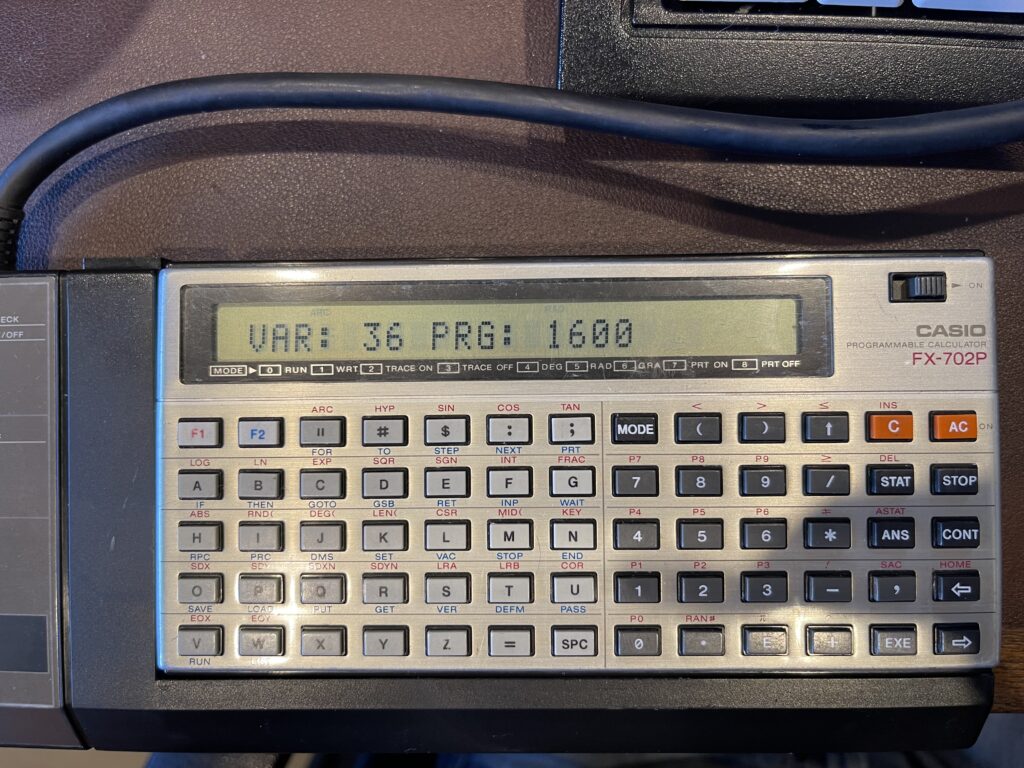
Variable spaces are added in groups of 10, meaning DEFM 1 would add 10 to the base of 26 spaces, for a total of 36 spaces.
Unfortunately, the array support on the FX-702P does not incorporate the built-in locations and combine with the DEFM allocation. For example, A(0) is not the same as A, and A(1) is not the same as B, etc. Therefore, built-in variable allocations A – Z which are unused by my program cannot easily be reused to store font bitmap data. Variables A – Z are completely separate from A(n) allocated by DEFM.
Building the Font Data
For this version of the banner program, I copied the bitmap data from the PC-4 version. The method for storing and retrieving is the same. In the example below, I take the bitmap for the letter “Z” and transpose it in it’s printed form. Note that dashes are used instead of spaces for illustration purposes. Also note that the font bitmap will be expanded by a factor of 2 horizontally when printed. For example, each zero will be two spaces, each one will be two X’s:
BYTE 1: 01100001
BYTE 2: 01010001
BYTE 3: 01001001
BYTE 4: 01000101
BYTE 5: 01000011

Desired Output:

--XXXX--------XX  Direction
--XX--XX------XX      |
--XX----XX----XX      |
--XX------XX--XX      |
--XX--------XXXX     \|/
Because the font is 7 pixels wide, the 8th bit is always zero. Each character needs 5 rows of data. These five bytes above can be represented in decimal form as 97, 81, 73, 69, 67.
Since there is no bitwise AND function for the FX-702P, I need to inspect the lowest order bit first, then right shift, and repeat. In other versions of the banner program, I was able to read the bits from left to right. In this version, I can only read them right to left. This results in the “Z” being printed mirrored:
Actual Output:

XX--------XXXX--  Direction
XX------XX--XX--      |
XX----XX----XX--      |
XX--XX------XX--      |
XXXX--------XX--     \|/
I took the font bitmap data from my previous versions of the banner program and mirrored the bits:
BYTE 1: 01000011
BYTE 2: 01000101
BYTE 3: 01001001
BYTE 4: 01010001
BYTE 5: 01100001
The decimal form for each of these bytes would be 67, 69, 73, 81, 97. I did the same “mirroring” for all of the characters A – Z and numbers 0 – 2. This way the output to the printer is now in the correct order. Now that I have the format of the font bitmap data needed, I need a way to store this into the FX-702P.
Using Less Memory for the Font Data
The font bitmap data in the format I created is 7 bits per row (round up to a byte, 8 bits), and 5 rows per character. There is a total of 30 characters, or 150 bytes. This includes the characters A – Z, a space, and numbers 0 – 2. With only 56 variable spaces and 1,440 steps for the program, I could not possibly use the same format I used for many of the other pocket computers that had more memory available.
The FX-702P uses 8 bytes per variable, the same amount for strings or integer values. It already allocates A – Z (or A$ – Z$) and this memory is built-in and separate from the program memory. Unfortunately, I cannot easily use some of this built-in variable space along with array space allocated using DEFM. I need to borrow spaces from the program memory for the bitmap data using DEFM x.
I do have enough memory to store each row of bitmap data (150 rows in total) into variables by using one variable per row. This could be accomplished by using DEFM 15. This would leave 480 bytes for the program itself. I need far less than 480 bytes for the banner program, so this is a possibility.
However, that is not only a waste of memory space, but it leaves little to no room for other programs. Instead, I need to use more than a byte’s worth of font data per variable space. By packing more font bitmap bytes into each variable, I am able to use more of the 8 bytes already allocated per variable space, and pack more into the same space.
My approach is to pack 4 bytes (or 4 rows of font data) into each variable location. The font data for each character has 5 bytes, one for each row in the character. This requires a total of only 37 variable locations to store all characters from A – Z, the space character, and numbers 0 – 2, which includes 5 rows of 7 bits per character.

For example, the numbers highlighted above (the left column) represent the 5 bytes for the letter “Z”. The data is read by the program from top to bottom, right to left. This means, the data would be read as 97, 81, 73, 69, 67. Notice how the last two bytes in the sequence for the letter “Z” are on the next line, and the first three bytes start in the middle of the row.
The column of numbers on the right is simply the result of “packing” the four values on the left into a single value. For example, if I assign a letter from A to D (from left to right) on each of the four bytes, I can describe the packing as a series of left shifts, using the following example:
(A * 128 * 128 * 128) + (B * 128 * 128) + (C * 128) + DBecause the font bitmap data never uses the 8th bit (it’s only 7 bits wide), I left shift by 7 bits each time, or by the value of 128. This avoids too large of a number which exceeds the computational limit of the pocket computer.
Note that the bytes are stored in reverse order and the bits are mirrored for each character. This is due to how I have to read each bit, and the limitations of the FX-702P’s BASIC commands available.
The data stored in the above format is for the characters A – Z, a space, and numbers 0 – 2. This method consumed only 37 variable locations, from an additional 40 variables using the DEFM 4 statement. This translates into an additional 320 bytes of memory borrowed from the program memory.
Loading the Font Bitmap Data
I wrote a program which inputs the font bitmap data into a variable array, leaving some room at the beginning of that array for working variables for the banner program:
10 FOR A = 0 TO 37 : INP A(A) : NEXT ANote that with the FX-702P, variable indexes start at 0, not 1. I then ran the program above and typed in the following numbers:
76616223
155181215
137337673
136880321
131096831
154297599
152190913
137338952
267625665
266470408
138403968
136331520
18866303
267407636
2113665
67506303
17055743
137346948
267362497
101852232
139550910
160579517
153917642
134849737
135282624
2113790
6502526
6276720
209699084
207946772
33802336
154231264
12497
130023424
131359941
4182144
145805440
154163401
The data above is the “packed” bytes of font bitmap data, in the order of A – Z, a space, and numbers 0 – 2.
After entering the bitmap data manually, I saved the variables to tape, so they do not need to be manually entered again:
PUT "DATA" $,A,A(37)This data can then be loaded again if needed, using:
DEFM 4
GET "DATA" $,A,A(37)
Now that I found a method to store the font bitmap data and character index data with limited BASIC support and limited memory, I then began to solve for the retrieval of the font data (using the special $ variable) given the user character input.
Reading the Font Data
The banner program needs to have a method to read each row of font data and examine each bit in the row. There also needs to be a method to either print characters without an automatic line feed or a way to perform string concatenation. The FX-702P printer supports multiple PRT statements on the same line, without an automatic line feed. Therefore, string concatenation is not needed.
Similar to the PC-1 and PC-4, I cannot use bitwise AND or similar logic to examine each bit in each row of font data. However, I was able to use the same method to determine if the lowest order bit is a zero or one based on even or odd value of the variable. I then used integer division to “right shift” the value to examine the next bit and so on.
The FX-702P does support string inspection commands MID and LEN but does not have any statement to convert a character to an integer. I used the special $ variable, which can hold up to 30 characters, for the basis of my own index function to convert a character to an index. D$ contains the letter to print from the user and A will have the index to the bitmap data:
500 FOR A = 1 TO 30 : IF D$ = MID(A, 1); A = A - 1 : GOTO 15
510 NEXT A : GOTO 10
In order for the above function to work, I needed to initialize the $ variable with the letters A – Z, a space, and numbers 0, 1, and 2:
$ = "ABCDEFGHIJKLMNOPQRSTUVWXYZ 012"Because the $ variable is limited to 30 characters, I could not fit A – Z, the space, and 0 – 9. This means I can support only letters A – Z and a space, then three more characters, if desired. In this case, I added numbers 0, 1, and 2. In the function above, if the input from the user is any other character outside of this range, we fall out from line 510 and ask the user for the next character.
Since I am packing 4 bytes into each variable location, this adds a bit of complexity for getting to the first bit in the character to be printed. This is because each character of font bitmap data needs 5 rows, and I am storing 4 rows per variable location. Not every character’s bitmap data directly lines up to a variable location.
Since A points to the character index to be printed, this needs to be converted to the variable index (from 0 to 37) and we need the bit location within that variable for where the font data begins for the selected character. Since there are 4 rows of font data per variable location in the array, and each character has 5 rows of font data, the conversion is fairly simple. Lines 10 – 20 below perform this conversion:
10 INP "LETTER", D$ : GOTO 500
15 A = A * 5 / 4 : MODE 7
20 F = (A - INT A) * 28 : A = INT A : B = A(A) : IF F = 0 THEN 40
30 FOR C = F TO 1 STEP -1 : GSB 300 : NEXT C
40 F = 28 - F
Since the first row of font data might not align with the first bit in the variable location, the variable F above is used to calculate where our starting bit actually is for the first row of font data. This is done by taking the fraction part (or remainder) of A and converting the result to the number of bits we need to right shift by (throw away or skip over).
On line 40, I am re-using the variable F to keep track of how many bits are remaining in this variable location before we have to load the next location to continue printing the rest of the current character.
With the storage and retrieval of the font bitmap data solved for, I then focused on the printing of each row.
The FP-10 printer does not have an automatic line feed after each print command. Therefore, I used the print command for each bit in the row:
50 FOR E = 1 TO 5 : PRT "  "; : FOR C = 1 TO 7
60 GSB 300 : IF D = B ; PRT "  "; : GOTO 80
70 PRT "XX";
80 F = F - 1 : NEXT C : PRT ""
The FP-10 printer can print 20 characters per line. The font width is 7 characters, and the printer width unfortunately is one character short for a perfect match for a 1:3 scale upwards. This means a scale of 1:2 is the most we can do for printing each character. This leaves 3 character spaces on the top and bottom of the banner.
I have included the WAV files for both the data and program below, as well as the program listing. Before loading the banner data file, use DEFM 4 to allocate space:
DEFM 4
GET "DATA" $,A,A(37)To load the banner program:
LOAD "BANNER" CASIO FX-702P BANNER PROGRAM VERSION 1.0
5 WAIT 0
10 INP "LETTER", D$ : GOTO 500
15 A = A * 5 / 4 : MODE 7
20 F = (A - INT A) * 28 : A = INT A : B = A(A) : IF F = 0 THEN 40
30 FOR C = F TO 1 STEP -1 : GSB 300 : NEXT C
40 F = 28 - F
50 FOR E = 1 TO 5 : PRT " "; : FOR C = 1 TO 7
60 GSB 300 : IF D = B ; PRT " "; : GOTO 80
70 PRT "XX";
80 F = F - 1 : NEXT C : PRT ""
90 IF F = 0 ; B = A(A + 1)
100 NEXT E
110 PRT "" : PRT "" : MODE 8 : GOTO 10
300 D = B / 2 : B = INT D : RET
500 FOR A = 1 TO 30 : IF D$ = MID(A, 1); A = A - 1 : GOTO 15
510 NEXT A : GOTO 10A - Letter index
B - Font Row Value
C - Font Row Loop
D - Temp
E - Shift loop
F - Bits left in font row
A(0-37) - Font bitmapThe banner program requires 263 steps and the font data requires 320 spaces. This leaves the FX-702P with 1,097 steps free for other programs.
While I was easily able to reuse almost all of the PC-4 version of the banner program as-is for this model, the BASIC functions in the FX-702P varied a bit from all other pocket computers for some commands, such as GSB, RET, INP, PRT.
Further, I was not able to break out of a FOR/NEXT loop via RET command without receiving a nesting error. For example, on line 500, this was originally a subroutine on the PC-4, with an RTN (return) instead of GOTO 15. However, on the FX-702P, it did not like a return in the middle of a FOR loop. A GSB (gosub) was permitted however, such as on line 60.
FX-602P and FX-502P
A few earlier models before the FX-702P were the FX-502P and the FX-602P. They shared the same 7-pin expansion port and can use the FA-1 or FA-2 cassette interface as well as the FP-10 printer.
These two earlier models did not have a printer “mode” per-se, and they were not BASIC programmable, and therefore there is no support to print within the programming steps or functions available.
From the FP-10 user guide I found, you can print the current screen by pressing INV SAVE INV EXE. This 4 key step to print the display is a bit awkward compared to all of the future pocket computer models which had a printer echo mode for example. This would automatically print everything on the screen, much like a typical printing calculator would.
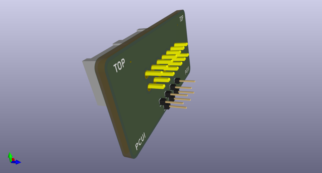
Pocket Computer Universal Interface (PCUI)
The Pocket Computer Universal Interface (PCUI) works with this series, including the FX-702P, with the same 7-pin interface port. The PCUI can be used as a printer cassette interface since the printer cassette is not as easy to find these days.

The PCUI has both CMOS and TTL level interface capabilities, and luckily this series’ expansion port is CMOS level.
The PCUI can save programs and variable contents from the FX-702P to its micro SD card and load programs from the micro SD card back to the FX-702P using SAVE and LOAD as with the cassette interface. The 7-pin connector has a clock and serial digital line for I/O, and the format is serial at CMOS level. The framing requires parity and stop bits and quite a bit of timing accuracy to sync.
In addition to emulating the cassette interface, the PCUI also emulates the printer interface, allowing you to use a standard line printer such as a dot matrix or any other parallel or serial interface printer.
The PCUI allows you to use an inexpensive thermal printer for example, readily available, without being limited to the FP-10 spark printer and trying to find extra aluminum coated paper these days.
Final Thoughts
The FX-702P was an interesting model, being the first Casio model to support BASIC. This could be considered Casio’s equivalent to the Sharp PC-1210 (or the PC-1211). The FP-10 mini electro printer was unique to me, in that it required aluminum coated paper for printing. Of course, there is a finite supply of this paper, if it can ever be found again, making this printer all but obsolete.
Luckily, at the time of the writing of this post, I was able to find NOS aluminum paper for the Quick Printer II. Although I had to cut the paper to the correct width, and the thickness is a bit more than the original Casio paper, it did work.
With short supply of paper, it is only a matter of time before the printer is completely obsolete. This is almost the case with the plotter printers I have, which require specific pens which are no longer manufactured. Even though those pens can be refilled, eventually they will wear to the point where they will no longer work.
Seeing the printer in action is an experience, and, there is not only the visual aspect of the sparking as it prints, but the burning aluminum odor adds to the experience. This is quite a unique printer across all of the other pocket computer printers I have come across.